ATmega169P
27.3 External Clock Drive Waveforms
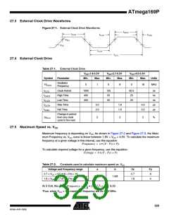
Figure 27-1. External Clock Drive Waveforms
V
IH1
V
IL1
27.4 External Clock Drive
Table 27-1. External Clock Drive
VCC=1.8-5.5V
VCC=2.7-5.5V
VCC=4.5-5.5V
Symbol
Parameter
Min.
Max.
Min.
Max.
Min.
Max.
Units
Oscillator
Frequency
1/tCLCL
0
1
0
8
0
16
MHz
tCLCL
tCHCX
tCLCX
tCLCH
tCHCL
Clock Period
High Time
Low Time
Rise Time
Fall Time
1000
400
125
50
62.5
25
ns
ns
ns
µs
µs
400
50
25
2.0
2.0
1.6
1.6
0.5
0.5
Change in period
from one clock
cycle to the next
∆tCLCL
2
2
2
ꢀ
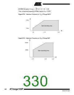
27.5 Maximum Speed vs. VCC
Maximum frequency is depending on VCC. As shown in Figure 27-2 and Figure 27-3, the Maxi-
mum Frequency vs. VCC curve is linear between 1.8V < VCC < 4.5V. To calculate the maximum
frequency at a given voltage in this interval, use this equation:
Frequency = a • (V – Vx) + Fy
To calculate required voltage for a given frequency, use this equation::
Voltage = b • (F – Fy) + Vx
Table 27-2. Constants used to calculate maximum speed vs. VCC
Voltage and Frequency range
2.7 < VCC < 4.5 or 8 < Frq < 16
1.8 < VCC < 2.7 or 4 < Frq < 8
a
b
Vx
2.7
1.8
Fy
8
8/1.8
1.8/8
4
8
1,8
-------
At 3 Volt, this gives:Frequency =
• (3 – 2,7) + 8 = 9,33
Thus, when VCC = 3V, maximum frequency will be 9.33 MHz.
329
8018A–AVR–03/06

 ATMEL [ ATMEL ]