ATmega169P
The Timer/Counter Overflow Flag (TOV1) is set according to the mode of operation selected by
the WGM13:0 bits. TOV1 can be used for generating a CPU interrupt.
14.5 Input Capture Unit
The Timer/Counter incorporates an Input Capture unit that can capture external events and give
them a time-stamp indicating time of occurrence. The external signal indicating an event, or mul-
tiple events, can be applied via the ICP1 pin or alternatively, via the analog-comparator unit. The
time-stamps can then be used to calculate frequency, duty-cycle, and other features of the sig-
nal applied. Alternatively the time-stamps can be used for creating a log of the events.
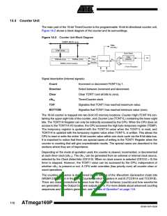
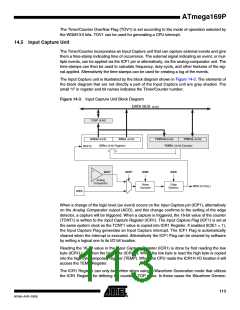
The Input Capture unit is illustrated by the block diagram shown in Figure 14-3. The elements of
the block diagram that are not directly a part of the Input Capture unit are gray shaded. The
small “n” in register and bit names indicates the Timer/Counter number.
Figure 14-3. Input Capture Unit Block Diagram
DATA BUS (8-bit)
TEMP (8-bit)
ICRnH (8-bit)
ICRnL (8-bit)
TCNTnH (8-bit)
TCNTnL (8-bit)
ICRn (16-bit Register)
TCNTn (16-bit Counter)
WRITE
ACO*
ACIC*
ICNC
ICES
Analog
Comparator
Noise
Canceler
Edge
Detector
ICFn (Int.Req.)
ICPn
When a change of the logic level (an event) occurs on the Input Capture pin (ICP1), alternatively
on the Analog Comparator output (ACO), and this change confirms to the setting of the edge
detector, a capture will be triggered. When a capture is triggered, the 16-bit value of the counter
(TCNT1) is written to the Input Capture Register (ICR1). The Input Capture Flag (ICF1) is set at
the same system clock as the TCNT1 value is copied into ICR1 Register. If enabled (ICIE1 = 1),
the Input Capture Flag generates an Input Capture interrupt. The ICF1 Flag is automatically
cleared when the interrupt is executed. Alternatively the ICF1 Flag can be cleared by software
by writing a logical one to its I/O bit location.
Reading the 16-bit value in the Input Capture Register (ICR1) is done by first reading the low
byte (ICR1L) and then the high byte (ICR1H). When the low byte is read the high byte is copied
into the high byte temporary register (TEMP). When the CPU reads the ICR1H I/O location it will
access the TEMP Register.
The ICR1 Register can only be written when using a Waveform Generation mode that utilizes
the ICR1 Register for defining the counter’s TOP value. In these cases the Waveform Genera-
113
8018A–AVR–03/06

 ATMEL [ ATMEL ]