24.3.4
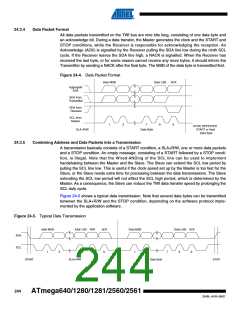
Data Packet Format
All data packets transmitted on the TWI bus are nine bits long, consisting of one data byte and
an acknowledge bit. During a data transfer, the Master generates the clock and the START and
STOP conditions, while the Receiver is responsible for acknowledging the reception. An
Acknowledge (ACK) is signalled by the Receiver pulling the SDA line low during the ninth SCL
cycle. If the Receiver leaves the SDA line high, a NACK is signalled. When the Receiver has
received the last byte, or for some reason cannot receive any more bytes, it should inform the
Transmitter by sending a NACK after the final byte. The MSB of the data byte is transmitted first.
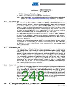
Figure 24-4. Data Packet Format
Data MSB
Data LSB
ACK
Aggregate
SDA
SDA from
Transmitter
SDA from
Receiver
SCL from
Master
1
2
7
8
9
STOP, REPEATED
START or Next
Data Byte
SLA+R/W
Data Byte
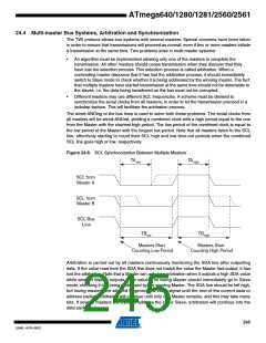
24.3.5
Combining Address and Data Packets into a Transmission
A transmission basically consists of a START condition, a SLA+R/W, one or more data packets
and a STOP condition. An empty message, consisting of a START followed by a STOP condi-
tion, is illegal. Note that the Wired-ANDing of the SCL line can be used to implement
handshaking between the Master and the Slave. The Slave can extend the SCL low period by
pulling the SCL line low. This is useful if the clock speed set up by the Master is too fast for the
Slave, or the Slave needs extra time for processing between the data transmissions. The Slave
extending the SCL low period will not affect the SCL high period, which is determined by the
Master. As a consequence, the Slave can reduce the TWI data transfer speed by prolonging the
SCL duty cycle.
Figure 24-5 shows a typical data transmission. Note that several data bytes can be transmitted
between the SLA+R/W and the STOP condition, depending on the software protocol imple-
mented by the application software.
Figure 24-5. Typical Data Transmission
Addr MSB
Addr LSB R/W
ACK
Data MSB
Data LSB ACK
SDA
SCL
1
2
7
8
9
1
2
7
8
9
START
SLA+R/W
Data Byte
STOP
244
ATmega640/1280/1281/2560/2561
2549L–AVR–08/07

 ATMEL [ ATMEL ]