ATmega640/1280/1281/2560/2561
Writing this bit to one enables interrupt on the UDREn Flag. A Data Register Empty interrupt will
be generated only if the UDRIE bit is written to one, the Global Interrupt Flag in SREG is written
to one and the UDREn bit in UCSRnA is set.
• Bit 4 - RXENn: Receiver Enable
Writing this bit to one enables the USART Receiver in MSPIM mode. The Receiver will override
normal port operation for the RxDn pin when enabled. Disabling the Receiver will flush the
receive buffer. Only enabling the receiver in MSPI mode (i.e. setting RXENn=1 and TXENn=0)
has no meaning since it is the transmitter that controls the transfer clock and since only master
mode is supported.
• Bit 3 - TXENn: Transmitter Enable
Writing this bit to one enables the USART Transmitter. The Transmitter will override normal port
operation for the TxDn pin when enabled. The disabling of the Transmitter (writing TXENn to
zero) will not become effective until ongoing and pending transmissions are completed, i.e.,
when the Transmit Shift Register and Transmit Buffer Register do not contain data to be trans-
mitted. When disabled, the Transmitter will no longer override the TxDn port.
• Bit 2:0 - Reserved Bits in MSPI mode
When in MSPI mode, these bits are reserved for future use. For compatibility with future devices,
these bits must be written to zero when UCSRnB is written.
23.6.4
UCSRnC – USART MSPIM Control and Status Register n C
Bit
7
6
5
4
3
-
2
UDORDn
R/W
1
UCPHAn
R/W
0
UCPOLn
R/W
UMSELn1
UMSELn0
-
-
UCSRnC
Read/Write
R/W
R/W
R
0
R
0
R
0
Initial Value
0
0
1
1
0
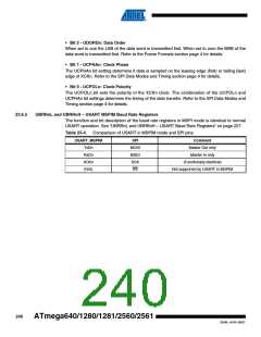
• Bit 7:6 - UMSELn1:0: USART Mode Select
These bits select the mode of operation of the USART as shown in Table 23-3. See “UCSRnC –
USART Control and Status Register n C” on page 226 for full description of the normal USART
operation. The MSPIM is enabled when both UMSELn bits are set to one. The UDORDn,
UCPHAn, and UCPOLn can be set in the same write operation where the MSPIM is enabled.
Table 23-3. UMSELn Bits Settings
UMSELn1
UMSELn0
Mode
0
0
1
1
0
1
0
1
Asynchronous USART
Synchronous USART
(Reserved)
Master SPI (MSPIM)
• Bit 5:3 - Reserved Bits in MSPI mode
When in MSPI mode, these bits are reserved for future use. For compatibility with future devices,
these bits must be written to zero when UCSRnC is written.
239
2549L–AVR–08/07

 ATMEL [ ATMEL ]