ATmega640/1280/1281/2560/2561
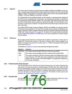
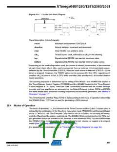
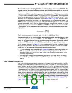
Figure 20-2. Counter Unit Block Diagram
TOVn
(Int.Req.)
DATA BUS
TOSC1
TOSC2
count
clear
T/C
Oscillator
clk Tn
TCNTn
Control Logic
Prescaler
direction
clk
bottom
top
I/O
Signal description (internal signals):
count
direction
clear
Increment or decrement TCNT2 by 1.
Selects between increment and decrement.
Clear TCNT2 (set all bits to zero).
clkTn
Timer/Counter clock, referred to as clkT2 in the following.
Signalizes that TCNT2 has reached maximum value.
Signalizes that TCNT2 has reached minimum value (zero).
top
bottom
Depending on the mode of operation used, the counter is cleared, incremented, or decremented
at each timer clock (clkT2). clkT2 can be generated from an external or internal clock source,
selected by the Clock Select bits (CS22:0). When no clock source is selected (CS22:0 = 0) the
timer is stopped. However, the TCNT2 value can be accessed by the CPU, regardless of
whether clkT2 is present or not. A CPU write overrides (has priority over) all counter clear or
count operations.
The counting sequence is determined by the setting of the WGM21 and WGM20 bits located in
the Timer/Counter Control Register (TCCR2A) and the WGM22 located in the Timer/Counter
Control Register B (TCCR2B). There are close connections between how the counter behaves
(counts) and how waveforms are generated on the Output Compare outputs OC2A and OC2B.
For more details about advanced counting sequences and waveform generation, see “Modes of
Operation” on page 177.
The Timer/Counter Overflow Flag (TOV2) is set according to the mode of operation selected by
the WGM22:0 bits. TOV2 can be used for generating a CPU interrupt.
20.4 Modes of Operation
The mode of operation, i.e., the behavior of the Timer/Counter and the Output Compare pins, is
defined by the combination of the Waveform Generation mode (WGM22:0) and Compare Output
mode (COM2x1:0) bits. The Compare Output mode bits do not affect the counting sequence,
while the Waveform Generation mode bits do. The COM2x1:0 bits control whether the PWM out-
put generated should be inverted or not (inverted or non-inverted PWM). For non-PWM modes
the COM2x1:0 bits control whether the output should be set, cleared, or toggled at a compare
match (See “Compare Match Output Unit” on page 183.).
For detailed timing information refer to “Timer/Counter Timing Diagrams” on page 184.
177
2549L–AVR–08/07

 ATMEL [ ATMEL ]