ATmega640/1280/1281/2560/2561
20. 8-bit Timer/Counter2 with PWM and Asynchronous Operation
Timer/Counter2 is a general purpose, single channel, 8-bit Timer/Counter module. The main
features are:
• Single Channel Counter
• Clear Timer on Compare Match (Auto Reload)
• Glitch-free, Phase Correct Pulse Width Modulator (PWM)
• Frequency Generator
• 10-bit Clock Prescaler
• Overflow and Compare Match Interrupt Sources (TOV2, OCF2A and OCF2B)
• Allows Clocking from External 32 kHz Watch Crystal Independent of the I/O Clock
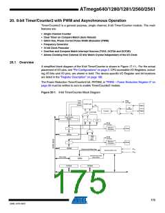
20.1 Overview
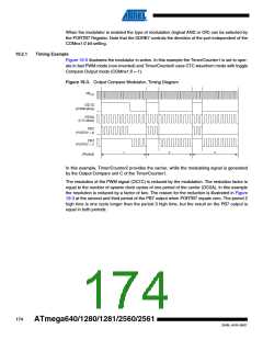
A simplified block diagram of the 8-bit Timer/Counter is shown in Figure 17-11.. For the actual
placement of I/O pins, see “Pin Configurations” on page 2. CPU accessible I/O Registers, includ-
ing I/O bits and I/O pins, are shown in bold. The device-specific I/O Register and bit locations
are listed in the “Register Description” on page 188.
The Power Reduction Timer/Counter2 bit, PRTIM2, in “PRR0 – Power Reduction Register 0” on
page 56 must be written to zero to enable Timer/Counter2 module.
Figure 20-1. 8-bit Timer/Counter Block Diagram
Count
TOVn
(Int.Req.)
Clear
Control Logic
Direction
clkTn
TOSC1
TOSC2
T/C
Oscillator
Prescaler
TOP
BOTTOM
clkI/O
Timer/Counter
TCNTn
=
=
0
OCnA
(Int.Req.)
Waveform
Generation
OCnA
OCnB
=
OCRnA
Fixed
TOP
Value
OCnB
(Int.Req.)
Waveform
Generation
=
OCRnB
clkI/O
Synchronized Status flags
Synchronization Unit
clkASY
asynchronous mode
select (ASn)
Status flags
ASSRn
TCCRnA
TCCRnB
175
2549L–AVR–08/07

 ATMEL [ ATMEL ]