ATmega640/1280/1281/2560/2561
The Timer/Counter Overflow Flag (TOVn) is set according to the mode of operation selected by
the WGMn3:0 bits. TOVn can be used for generating a CPU interrupt.
17.6 Input Capture Unit
The Timer/Counter incorporates an input capture unit that can capture external events and give
them a time-stamp indicating time of occurrence. The external signal indicating an event, or mul-
tiple events, can be applied via the ICPn pin or alternatively, for the Timer/Counter1 only, via the
Analog Comparator unit. The time-stamps can then be used to calculate frequency, duty-cycle,
and other features of the signal applied. Alternatively the time-stamps can be used for creating a
log of the events.
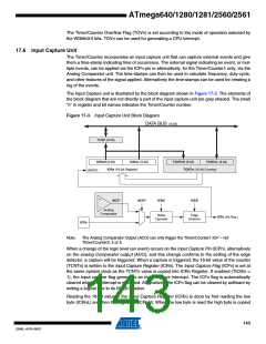
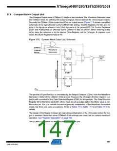
The Input Capture unit is illustrated by the block diagram shown in Figure 17-3. The elements of
the block diagram that are not directly a part of the input capture unit are gray shaded. The small
“n” in register and bit names indicates the Timer/Counter number.
Figure 17-3. Input Capture Unit Block Diagram
DATA BUS (8-bit)
TEMP (8-bit)
ICRnH (8-bit)
ICRnL (8-bit)
TCNTnH (8-bit)
TCNTnL (8-bit)
ICRn (16-bit Register)
TCNTn (16-bit Counter)
WRITE
ACO*
ACIC*
ICNC
ICES
Analog
Comparator
Noise
Canceler
Edge
Detector
ICFn (Int.Req.)
ICPn
Note:
The Analog Comparator Output (ACO) can only trigger the Timer/Counter1 ICP – not
Timer/Counter3, 4 or 5.
When a change of the logic level (an event) occurs on the Input Capture Pin (ICPn), alternatively
on the analog Comparator output (ACO), and this change confirms to the setting of the edge
detector, a capture will be triggered. When a capture is triggered, the 16-bit value of the counter
(TCNTn) is written to the Input Capture Register (ICRn). The Input Capture Flag (ICFn) is set at
the same system clock as the TCNTn value is copied into ICRn Register. If enabled (TICIEn =
1), the input capture flag generates an input capture interrupt. The ICFn flag is automatically
cleared when the interrupt is executed. Alternatively the ICFn flag can be cleared by software by
writing a logical one to its I/O bit location.
Reading the 16-bit value in the Input Capture Register (ICRn) is done by first reading the low
byte (ICRnL) and then the high byte (ICRnH). When the low byte is read the high byte is copied
143
2549L–AVR–08/07

 ATMEL [ ATMEL ]