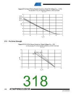
are controlled by the Power Reduction Register. See “Power Reduction Register” on page 42 for
details.
Table 27-1. Additional Current Consumption for the different I/O modules (absolute values)
PRR bit
Typical numbers
CC = 3V, F = 8MHz
V
VCC = 5V, F = 16MHz
PRPSC2
PRPSC1
PRPSC0
PRTIM1
PRTIM0
PRSPI
350 uA
350 uA
350 uA
300 uA
200 uA
250 uA
550 uA
350 uA
1.3 mA
1.3 mA
1.3 mA
1.15 mA
0.75 mA
0.9 mA
2 mA
PRUSART
PRADC
1.3 mA
Table 27-2. Additional Current Consumption (percentage) in Active and Idle mode
Additional Current consumption
compared to Active with external
clock
(see Figure 27-1 and Figure 27-2)
Additional Current consumption
compared to Idle with external clock
(see Figure 27-5 and Figure 27-6)
PRR bit
PRPSC2
PRPSC1
PRPSC0
PRTIM1
PRTIM0
PRSPI
10%
25%
25%
25%
22%
11%
14%
36
10%
10%
8.5%
4.3%
5.3%
15.6
PRUSART
PRADC
10.5%
25%
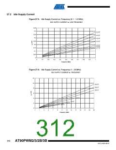
It is possible to calculate the typical current consumption based on the numbers from Table 27-2
for other VCC and frequency settings than listed in Table 27-1.
27.2.1.1
Example 1
Calculate the expected current consumption in idle mode with USART, TIMER1, and SPI
enabled at VCC = 3.0V and F = 1MHz. From Table 27-2, third column, we see that we need to
add 18% for the USART, 26% for the SPI, and 11% for the TIMER1 module. Reading from Fig-
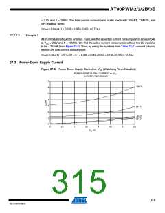
ure 27-5, we find that the idle current consumption is ~0,17mA at VCC = 3.0V and F = 1MHz. The
total current consumption in idle mode with USART0, TIMER1, and SPI enabled, gives:
ICCtotal ≈ 0.17mA • (1 + 0.36 + 0.22 + 0.14) ≈ 0.29mA
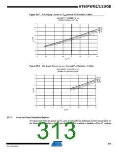
27.2.1.2
Example 2
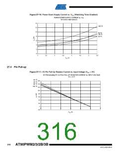
Same conditions as in example 1, but in active mode instead. From Table 27-2, second column
we see that we need to add 3.3% for the USART, 4.8% for the SPI, and 2.0% for the TIMER1
module. Reading from Figure 27-1, we find that the active current consumption is ~0,6mA at VCC
314
AT90PWM2/3/2B/3B
4317J–AVR–08/10

 ATMEL [ ATMEL ]