AT90PWM2/3/2B/3B
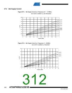
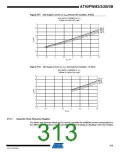
Figure 27-7. IIdle Supply Current vs. VCC (Internal RC Oscillator, 8 MHz)
IDLE SUPPLY CURRENT vs. VCC
INTERNAL RC OSCILLATOR, 8 MHz
4
3,5
3
105 °C
85 °C
25 °C
-40 °C
2,5
2
1,5
1
0,5
0
2
2,5
3
3,5
4
4,5
5
5,5
V
CC (V)
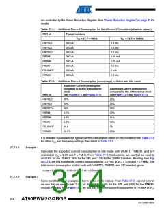
Figure 27-8. Idle Supply Current vs. VCC (Internal PLL Oscillator, 16 MHz)
IDLE SUPPLY CURRENT vs. VCC
INTERNAL PLL OSCILLATOR, 16 MHz
9
8
7
6
5
4
3
2
1
0
105 °C
85 °C
25 °C
-40 °C
2
2,5
3
3,5
4
4,5
5
5,5
VCC (V)
27.2.1
Using the Power Reduction Register
The tables and formulas below can be used to calculate the additional current consumption for
the different I/O modules in Active and Idle mode. The enabling or disabling of the I/O modules
313
4317J–AVR–08/10

 ATMEL [ ATMEL ]