AT89S52
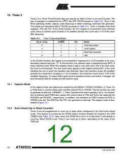
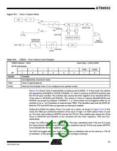
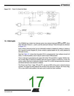
Figure 10-1. Timer in Capture Mode
÷12
OSC
C/T2 = 0
C/T2 = 1
TH2
TL2
TF2
OVERFLOW
CONTROL
TR2
CAPTURE
T2 PIN
RCAP2H RCAP2L
EXF2
TRANSITION
DETECTOR
TIMER 2
INTERRUPT
T2EX PIN
CONTROL
EXEN2
Table 10-2. T2MOD – Timer 2 Mode Control Register
T2MOD Address = 0C9H
Reset Value = XXXX XX00B
Not Bit Addressable
–
7
–
6
–
5
–
4
–
3
–
2
T2OE
1
DCEN
0
Bit
Symbol
–
Function
Not implemented, reserved for future
Timer 2 Output Enable bit
T2OE
DCEN
When set, this bit allows Timer 2 to be configured as an up/down counter
Figure 10-2 shows Timer 2 automatically counting up when DCEN = 0. In this mode, two options
are selected by bit EXEN2 in T2CON. If EXEN2 = 0, Timer 2 counts up to 0FFFFH and then sets
the TF2 bit upon overflow. The overflow also causes the timer registers to be reloaded with the
16-bit value in RCAP2H and RCAP2L. The values in Timer in Capture ModeRCAP2H and
RCAP2L are preset by software. If EXEN2 = 1, a 16-bit reload can be triggered either by an
overflow or by a 1-to-0 transition at external input T2EX. This transition also sets the EXF2 bit.
Both the TF2 and EXF2 bits can generate an interrupt if enabled.
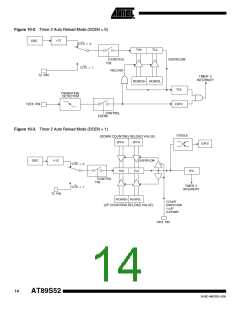
Setting the DCEN bit enables Timer 2 to count up or down, as shown in Figure 10-2. In this
mode, the T2EX pin controls the direction of the count. A logic 1 at T2EX makes Timer 2 count
up. The timer will overflow at 0FFFFH and set the TF2 bit. This overflow also causes the 16-bit
value in RCAP2H and RCAP2L to be reloaded into the timer registers, TH2 and TL2,
respectively.
A logic 0 at T2EX makes Timer 2 count down. The timer underflows when TH2 and TL2 equal
the values stored in RCAP2H and RCAP2L. The underflow sets the TF2 bit and causes 0FFFFH
to be reloaded into the timer registers.
The EXF2 bit toggles whenever Timer 2 overflows or underflows and can be used as a 17th bit
of resolution. In this operating mode, EXF2 does not flag an interrupt.
13
1919C–MICRO–3/05

 ATMEL [ ATMEL ]