AT90USB64/128
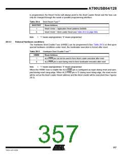
is programmed, the Reset Vector will always point to the Boot Loader Reset and the fuse can
only be changed through the serial or parallel programming interface.
Table 28-4. Boot Reset Fuse(1)
BOOTRST
Reset Address
1
0
Reset Vector = Application Reset (address 0x0000)
Reset Vector = Boot Loader Reset (see Table 28-8 on page 366)
Note:
1. “1” means unprogrammed, “0” means programmed
28.5.3
External Hardware conditions
The Hardware Boot Enable Fuse (HWBE) can be programmed (See Table 28-5) so that upon
special hardware conditions under reset, the bootloader execution is forced after reset.
Table 28-5. Hardware Boot Enable Fuse(1)
HWBE
Reset Address
1
0
ALE/HWB pin can not be used to force Boot Loader execution after reset
ALE/HWB pin is used during reset to force bootloader execution after reset
Note:
1. “1” means unprogrammed, “0” means programmed
When the HWBE fuse is enable the ALE/HWB pin is configured as input during reset and sam-
pled during reset rising edge. When ALE/HWB pin is ‘0’ during reset rising edge, the reset vector
will be set as the Boot Loader Reset address and the Boot Loader will be executed (See Figures
28-3).
357
7593A–AVR–02/06

 ATMEL [ ATMEL ]