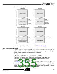
Table 28-2. Boot Lock Bit0 Protection Modes (Application Section)(1)
BLB0 Mode BLB02 BLB01 Protection
No restrictions for SPM or (E)LPM accessing the
Application section.
1
2
1
1
1
0
SPM is not allowed to write to the Application section.
SPM is not allowed to write to the Application section, and
(E)LPM executing from the Boot Loader section is not
allowed to read from the Application section. If Interrupt
Vectors are placed in the Boot Loader section, interrupts
are disabled while executing from the Application section.
3
4
0
0
0
1
(E)LPM executing from the Boot Loader section is not
allowed to read from the Application section. If Interrupt
Vectors are placed in the Boot Loader section, interrupts
are disabled while executing from the Application section.
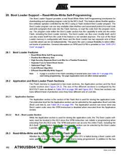
Note:
1. “1” means unprogrammed, “0” means programmed
Table 28-3. Boot Lock Bit1 Protection Modes (Boot Loader Section)(1)
BLB1 Mode BLB12 BLB11 Protection
No restrictions for SPM or (E)LPM accessing the Boot
Loader section.
1
2
1
1
1
0
SPM is not allowed to write to the Boot Loader section.
SPM is not allowed to write to the Boot Loader section,
and (E)LPM executing from the Application section is not
allowed to read from the Boot Loader section. If Interrupt
Vectors are placed in the Application section, interrupts
are disabled while executing from the Boot Loader
section.
3
4
0
0
0
(E)LPM executing from the Application section is not
allowed to read from the Boot Loader section. If Interrupt
Vectors are placed in the Application section, interrupts
are disabled while executing from the Boot Loader
section.
1
Note:
1. “1” means unprogrammed, “0” means programmed
28.5 Entering the Boot Loader Program
The bootloader can be executed with three different conditions:
28.5.1
28.5.2
Regular application conditions.
A jump or call from the application program. This may be initiated by a trigger such as a com-
mand received via USART, SPI or USB.
Boot Reset Fuse
The Boot Reset Fuse (BOOTRST) can be programmed so that the Reset Vector is pointing to
the Boot Flash start address after a reset. In this case, the Boot Loader is started after a reset.
After the application code is loaded, the program can start executing the application code. Note
that the fuses cannot be changed by the MCU itself. This means that once the Boot Reset Fuse
356
AT90USB64/128
7593A–AVR–02/06

 ATMEL [ ATMEL ]