AT90USB64/128
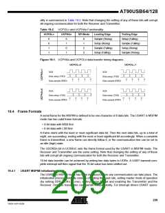
ality is summarized in Table 19-2. Note that changing the setting of any of these bits will corrupt
all ongoing communication for both the Receiver and Transmitter.
Table 19-2. UCPOLn and UCPHAn Functionality-
UCPOLn
UCPHAn
SPI Mode
Leading Edge
Sample (Rising)
Setup (Rising)
Sample (Falling)
Setup (Falling)
Trailing Edge
Setup (Falling)
Sample (Falling)
Setup (Rising)
Sample (Rising)
0
0
1
1
0
1
0
1
0
1
2
3
Figure 19-1. UCPHAn and UCPOLn data transfer timing diagrams.
UCPOL=0
UCPOL=1
XCK
XCK
Data setup (TXD)
Data sample (RXD)
Data setup (TXD)
Data sample (RXD)
XCK
XCK
Data setup (TXD)
Data sample (RXD)
Data setup (TXD)
Data sample (RXD)
19.4 Frame Formats
A serial frame for the MSPIM is defined to be one character of 8 data bits. The USART in MSPIM
mode has two valid frame formats:
• 8-bit data with MSB first
• 8-bit data with LSB first
A frame starts with the least or most significant data bit. Then the next data bits, up to a total of
eight, are succeeding, ending with the most or least significant bit accordingly. When a complete
frame is transmitted, a new frame can directly follow it, or the communication line can be set to
an idle (high) state.
The UDORDn bit in UCSRnC sets the frame format used by the USART in MSPIM mode. The
Receiver and Transmitter use the same setting. Note that changing the setting of any of these
bits will corrupt all ongoing communication for both the Receiver and Transmitter.
16-bit data transfer can be achieved by writing two data bytes to UDRn. A UART transmit com-
plete interrupt will then signal that the 16-bit value has been shifted out.
19.4.1
USART MSPIM Initialization
The USART in MSPIM mode has to be initialized before any communication can take place. The
initialization process normally consists of setting the baud rate, setting master mode of operation
(by setting DDR_XCKn to one), setting frame format and enabling the Transmitter and the
Receiver. Only the transmitter can operate independently. For interrupt driven USART opera-
209
7593A–AVR–02/06

 ATMEL [ ATMEL ]