AT90USB64/128
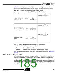
Table 18-1 contains equations for calculating the baud rate (in bits per second) and for calculat-
ing the UBRRn value for each mode of operation using an internally generated clock source.
Table 18-1. Equations for Calculating Baud Rate Register Setting
Equation for Calculating
Baud Rate(1)
Equation for Calculating
UBRR Value
Operating Mode
f
OSC
UBRRn = ----------------------- – 1
16BAUD
f
Asynchronous Normal
mode (U2Xn = 0)
OSC
BAUD = -----------------------------------------
16(UBRRn + 1)
f
OSC
UBRRn = -------------------- – 1
8BAUD
f
Asynchronous Double
Speed mode (U2Xn = 1)
OSC
BAUD = --------------------------------------
8(UBRRn + 1)
f
OSC
UBRRn = -------------------- – 1
2BAUD
f
Synchronous Master
mode
OSC
BAUD = --------------------------------------
2(UBRRn + 1)
Note:
1. The baud rate is defined to be the transfer rate in bit per second (bps)
BAUD
Baud rate (in bits per second, bps)
fOSC
System Oscillator clock frequency
UBRRn
Contents of the UBRRHn and UBRRLn Registers, (0-4095)
Some examples of UBRRn values for some system clock frequencies are found in Table 18-9 on
page 204.
18.2.2
Double Speed Operation (U2Xn)
The transfer rate can be doubled by setting the U2Xn bit in UCSRnA. Setting this bit only has
effect for the asynchronous operation. Set this bit to zero when using synchronous operation.
Setting this bit will reduce the divisor of the baud rate divider from 16 to 8, effectively doubling
the transfer rate for asynchronous communication. Note however that the Receiver will in this
case only use half the number of samples (reduced from 16 to 8) for data sampling and clock
recovery, and therefore a more accurate baud rate setting and system clock are required when
this mode is used. For the Transmitter, there are no downsides.
185
7593A–AVR–02/06

 ATMEL [ ATMEL ]