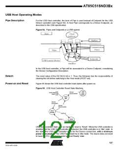
The Host controller enters in Suspend state when the USB bus is in Suspend state, i.e.
when the Host controller doesn’t generate the Start of Frame. In this state, the USB con-
sumption is minimum. The Host controller exits to the Suspend state when starting to
generate the SOF over the USB line.
Device Detection
Pipe Selection
A Device is detected by the USB controller when the USB bus if different from D+ and
D- low. In other words, when the USB Host Controller detects the Device pull-up on the
D+ line. To enable this detection, the Host Controller has to provide the Vbus power
supply to the Device.
The Device Disconnection is detected by the USB Host controller when the USB Idle
correspond to D+ and D- low on the USB line.
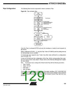
Prior to any operation performed by the CPU, the Pipe must first be selected. This is
done by:
•
•
Clearing PNUMS.
Setting PNUM with the Pipe number which will be managed by the CPU.
The CPU can then access to the various Pipe registers and data.
In the same manner, if the Pipe must be accessed by the DFC, it must first be selected.
This is done by:
•
•
•
Setting PNUMS.
Setting PNUM with the Pipe number which will be managed by the DFC.
Setting DFCRDY when the data-flow is ready to take place.
The DFC can then access to the banks (read / write).
The controller internally keeps in memory the PNUM for the CPU and the PNUM for the
DFC. In fact, there are 2 PNUM registers multiplexed by the PNUMS bit. Each of them
can be read or written by the CPU.
These two registers permits to easily switch from a Pipe under DFC data transfer to the
default control Pipe when a SETUP has to be sent, without reprogramming the EPNUM
register:
–
–
–
–
–
–
–
–
–
–
Set PNUMS,
PNUM = Pipex
Set DFCRDY when the DFC transfer is ready to take place,
...<DFC transfer>...
SETUP required on Pipe0,
Clear DFCRDY to freeze the DFC transfer,
PNUMS cleared,
PNUM = Pipe0
Manage Pipe0 data
Set DFCRDY. This resumes the DFC transfer.
128
AT85C51SND3Bx
7632A–MP3–03/06

 ATMEL [ ATMEL ]