AT24C21
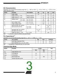
DC Characteristics
Applicable over recommended operating range from: TAI = -40°C to +85°C, TAC = 0°C to +70°C, VCC = +2.5V to +5.5V
(unless otherwise noted).
Symbol
VCC
ICC
Parameter
Test Condition
Min
Typ
Max
5.5
1.0
Units
V
Supply Voltage
2.5
Supply Current VCC = 5.0V
Supply Current VCC = 5.0V
READ at 100 KHz
WRITE at 100 KHz
0.4
2.0
mA
mA
ICC
3.0
ISB
Standby Current .......VCC = 2.5V
.......VCC = 5.0V
V
IN = VCC or VSS
3.0
4.0
µA
µA
VIN = VCC or VSS
VIN = VCC or VSS
VOUT = VCC or VSS
12.0
30.0
ILI
Input Leakage Current
Output Leakage Current
0.10
0.05
1.0
1.0
µA
µA
ILO
VIL
Input Low Level(1) SCL, SDA Pin
Input Low Level VCLK Pin
-0.6
V
CC × 0.3
V
V
V
VCC ≥ 2.7V
0.8
VCC < 2.7V
0.2 × VCC
VIH
Input High Level(1) SCL, SDA Pin
Input High Level VCLK Pin
V
CC × 0.7
VCC + 0.5
V
V
2.0
VOL
Output Low Level VCC = 3.0V
IOL = 2.1 mA
0.40
V
Note:
1. VIL min and VIH max are for reference only and not tested.
Pin Capacitance(1)
Applicable over recommended operating range from TA = 25°C, f = 1.0 MHz, VCC = +1.8V.
Symbol
CI/O
Test Condition
Max
8
Units
pF
Conditions
Input/Output Capacitance (SDA)
Input Capacitance (A0, A1, A2, SCL, VCLK)
VI/O = 0V
VIN = 0V
CIN
6
pF
Note:
1. This parameter is characterized and is not 100% tested.
Transmit-Only Mode
Symbol
Parameter
2.5-volt
Units
Min
Max
TVAA
Output valid from VCLK
VCLK high-time
500
ns
µs
µs
ns
ns
TVHIGH
TVLOW
TVHZ
4.0
4.7
VCLK low-time
Mode transition time
Transmit-Only power-up time
500
TVPU
0
3

 ATMEL [ ATMEL ]