APW7108
Ordering and Marking Information
Package Code
N : SSOP-28
APW7108
QA: QFN4x4-24
Operating Ambient Temperature Range
I : -40 to 85°C
Handling Code
Assembly Material
Handling Code
Temperature Range
Package Code
TR : Tape & Reel
Assembly Material
G : Halogen and Lead Free Device
APW7108
XXXXX
APW7108 N :
XXXXX - Date Code
APW7108 QA :
APW7108
XXXXX
XXXXX - Date Code
Note : ANPEC lead-free products contain molding compounds/die attach materials and 100% matte tin plate termination finish;
which are fully compliant with RoHS. ANPEC lead-free products meet or exceed the lead-free requirements of IPC/JEDEC J-STD-
020C for MSL classification at lead-free peak reflow temperature. ANPEC defines “Green” to mean lead-free (RoHS compliant) and
halogen free (Br or Cl does not exceed 900ppm by weight in homogeneous material and total of Br and Cl does not exceed
1500ppm by weight).
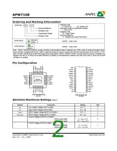
Pin Configuration
VCC
GND
LGATE1
PGND1
28
1
2
3
4
27 LGATE2
26
25
PGND2
PHASE2
PHASE1
UGATE1
5
6
24 UGATE2
UGATE1
1
18 UGATE2
17 BOOT2
16 ISEN2
15 EN2
23
22
21
20
BOOT2
ISEN2
EN2
BOOT1
ISEN1
EN1
BOOT1 2
7
8
ISEN1
3
Backside
Exposed Pad
EN1
VOUT1
VSEN1
4
5
6
14 VOUT2
13 VSEN2
9
VOUT1
VSEN1
VOUT2
10
19 VSEN2
18
17
16
OCSET1 11
OCSET2
SOFT2
PG2
12
SOFT1
13
14
NC
VIN
15 PG1
APW7108 (QFN4x4-24)
APW7108 (SSOP-28)
Top View
Top View
Absolute Maximum Ratings (Note 1)
Symbol
VCC
Parameter
VCC Supply Voltage (VCC to GND)
Input Power Voltage (VIN to GND)
BOOT Supply Voltage (BOOT to PHASE)
BOOT Supply Voltage (BOOT to GND)
UGATE Voltage (UGATE to PHASE)
Rating
Unit
V
-0.3 ~ 7
-0.3 ~ 28
-0.3 ~ 7
VIN
V
VBOOT
VBOOT-GND
V
-0.3 ~ 35
V
<400ns pulse width
-5 ~ VBOOT+0.3
V
V
>400ns pulse width
-0.3 ~ VBOOT+0.3
LGATE Voltage (LGATE to GND)
<400ns pulse width
>400ns pulse width
-5 ~ VCC+0.3
-0.3 ~ VCC+0.3
Copyright ã ANPEC Electronics Corp.
2
www.anpec.com.tw
Rev. A.4 - Jan., 2009

 ANPEC [ ANPEC ELECTRONICS COROPRATION ]