APL3512
Application Information
Input Capacitor
refer to the Recommended Operating Conditions), the
soft-start time will become internally controlled as if there
is no CSS, tSS=2ms when VIN=5V, for example. If a soft-
start capacitor is used, please make sure the CSS is in the
recommeded operating range.
A 1mF ceramic bypass capacitor from VIN to GND, located
near the APL3512, is strongly recommended to suppress
the ringing during short-circuit fault event. Without the by-
pass capacitor, the output short may cause sufficient ring-
ing on the input (from supply lead inductance) to damage
internal control circuitry.
Layout Consideration
The PCB layout should be carefully performed to maxi-
mize thermal dissipation and to minimize voltage drop,
droop and EMI. The following guidelines must be
considered:
Output Capacitor
A low-ESR 10mF MLCC, aluminum electrolytic or tanta-
lum between VOUT and GND is strongly recommended
to reduce the voltage droop during hot-attachment of
downstream peripheral. Higher-value output capacitor is
better when the output load is heavy. Additionally, bypass-
ing the output with a 0.1mF ceramic capacitor improves
the immunity of the device to short-circuit transients.
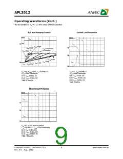
During soft-start process, the output bulk capacitor draws
inrush current from VIN. If the inrush current reaches
foldback current-limit threshold, namely 0.8A, the output
current will be clamped in 0.8A level. It will take longer to
complete the soft-start process since the soft-start rate
is controlled neither by internal soft-start nor by external
soft-start circuitry. When the COUT meets the following
formula, the soft-start will be controlled by foldback cur-
rent-limiting:
1. Please place the input capacitors near the VIN pin as
close as possible.
2. Output decoupling capacitors for load must be placed
near the load as close as possible for decoupling high-
frequency ripples.
3. Locate APL3512 and output capacitors near the load to
reduce parasitic resistance and inductance for excel-
lent load transient performance.
4. The negative pins of the input and output capacitors
and the GNDpin must be connected to the ground plane
of the load.
5. Keep VIN and VOUT traces as wide and short as possible.
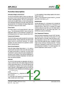
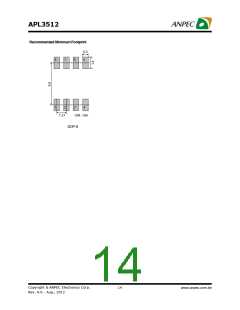
Recommended Minimum Footprint
COUT > (0.8xtSS)/VIN
Where,
tSS is 1ms when SS is open or tied to VIN, or obtained by
the tss equation, described in the paragraph of Soft-Start
in Functional Description section when CSS is used.
If the soft-start rate is controlled by the foldback current-
limiting, the soft-start time can be got by the following
equation:
0.075
tSS_Foldback = (COUT x VIN)/0.8
Soft-Start Capacitor
The APL3512 has a built-in adjustable soft-start control
for user to set an optimum soft-start time for the app-
lication. The soft-start time can be calculated by the
equation, described in the paragraph of Soft-Start in Func-
tional Description section. Please note that there are mini-
mum and maximum limitations of soft-start capacitor. If
the value of soft-start capacitor is less than the minimum
limitation or higher than the maximum limitation (please
0.037
0.02
Unit : Inch
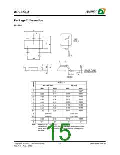
SOT-23-5
Copyright ã ANPEC Electronics Corp.
13
www.anpec.com.tw
Rev. A.6 - Aug., 2012

 ANPEC [ ANPEC ELECTRONICS COROPRATION ]