PRODUCT DATASHEET
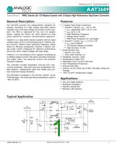
AAT2689
TM
SystemPower PMIC Solution for 12V Adapter Systems with 2-Output High Performance Step-Down Converters
Absolute Maximum Ratings1
Symbol
Description
Value
Units
VIN(HI), VEN1
VIN(LO)
VBST1-LX1
VCONTROL
VEN2
IN1, LX, EN1 to GND
IN2, VL1 to GND
BST1 to LX1
FB1, COMP1, RS1, OS1, OUT2 to GND
EN2 to GND
-0.3 to 30.0
-0.3 to 6.0
-0.3 to 6.0
-0.3 to VIN(LO) + 0.3
-0.3 to VIN2 + 0.3
12.0
V
V
V
V
V
IIN(PULSED)
TJ
TLEAD
IN to LX
A
°C
°C
Operating Junction Temperature Range
Maximum Soldering Temperature (at leads, 10 sec)
-40 to 150
300
Thermal Information
Symbol
Description
Thermal Resistance2
Maximum Power Dissipation3
Value
Units
ΘJA
PD
50
2.0
°C/W
W
1. Stresses above those listed in Absolute Maximum Ratings may cause permanent damage to the device. Functional operation at conditions other than the operating conditions
specified is not implied. Only one Absolute Maximum Rating should be applied at any one time.
2. Mounted on an FR4 board with exposed paddle connected to ground plane.
3. Derate 20mW/°C above 25°C ambient temperature.
w w w . a n a l o g i c t e c h . c o m
2689.2008.06.1.0
3

 ANALOGICTECH [ ADVANCED ANALOGIC TECHNOLOGIES ]