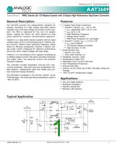
PRODUCT DATASHEET
AAT2689
TM
SystemPower PMIC Solution for 12V Adapter Systems with 2-Output High Performance Step-Down Converters
Pin Descriptions
Pin # Symbol Function
Input supply voltage pin for Channel 1 step-down (Buck) regulator. Connect both IN1 pins together. Connect
the input capacitor close to this pin for best noise performance.
1
IN1
Channel 1 step-down (Buck) regulator boost drive input pin. Connect the cathode of fast rectifier from this pin
and connect a 100nF capacitor from this pin to the Channel 1 switching node (LX) for internal hi-side MOSFET
gate drive.
2
BST1
Channel 1 step-down (Buck) regulator enable input pin. Active high enables internal linear regulator and
Channel 1 output.
Channel 1 output current sense pin. Connect a small signal resistor from this pin to the Channel 1 switching
node (LX) to enable over-current sense for step-down (Buck) converter.
Channel 1 output sense voltage pin. Connect to the output capacitor to enable over-current sense for step-
down (Buck) converter.
Compensation pin for Channel 1 step-down (Buck) regulator. Connect a series resistor and capacitor network
to compensate for the voltage mode control loop.
3
4
5
6
EN1
RS1
OS1
COMP1
Feedback input pin for Channel 1 step-down (Buck) converter. Connect an external resistor divider to this pin
to program the output voltage to the desired value.
Channel 2 linear low dropout (LDO) enable input pin. Active high.
Input supply voltage pin for Channel 2 linear low dropout (LDO) regulator. Connect a 2.2μF ceramic input
capacitor close to this pin.
7
8
9
FB1
EN2
IN2
Output of Channel 2 of linear low dropout (LDO) regulator. Connect a 2.2μF ceramic capacitor from this pin to
the GND pin.
Analog ground pin for LDO and Buck (step-down) controller. Tie to PCB ground plane.
Internal linear regulator for Channel 1 step-down (Buck) converter. Connect a 2.2μF/6.3V capacitor from this
10
11
12
OUT2
AGND
VL1
pin to the GND pin.
Ground pin for both channels. Power return pin for both channels. Connect returns of both channels input and
output capacitors close to this pin for best noise performance.
Input supply voltage pin for Channel 1 step-down (Buck) regulator. Connect both IN1 pins together. Connect
the input capacitor close to this pin for best noise performance.
13
14
GND
IN1
Channel 1 step-down (Buck) converter switching pin. Connect output inductor to this pin. Connect both LX1
pins together.
Channel 1 step-down (Buck) converter switching pin. Connect output inductor to this pin. Connect both LX1
pins together.
Exposed paddle 1 tied to ground. Connect to PCB heatsink for optimum thermal performance of internal LDO
device.
Exposed paddle 2 tied to drain of internal high side MOSFET. Connect to PCB heatsink for optimum thermal
performance of step-down (Buck) regulator.
15
LX1
LX1
GND
IN1
16
EP1
EP2
Pin Configuration
TDFN34-16 Dual Paddle
(Top View)
1
2
3
4
5
6
7
8
16
15
14
13
12
11
10
9
LX1
IN1
BST1
EN1
EP2
LX1
IN1
RS1
GND
VL1
OS1
EP1
AGND
OUT2
IN2
COMP1
FB1
EN2
w w w . a n a l o g i c t e c h . c o m
2
2689.2008.06.1.0

 ANALOGICTECH [ ADVANCED ANALOGIC TECHNOLOGIES ]