PRODUCT DATASHEET
AAT1145
SwitchRegTM
1.2A Step-Down Converter
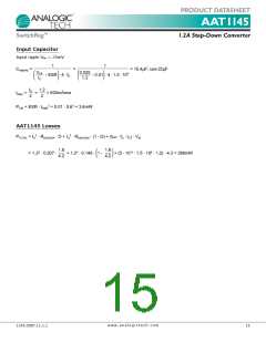
The input capacitor RMS ripple current varies with the
input and output voltage and will always be less than or
equal to half of the total DC load current.
ripple) are equivalent series resistance (ESR), equivalent
series inductance (ESL), and capacitance (C).
The output voltage droop due to a load transient is
dominated by the capacitance of the ceramic output
capacitor. During a step increase in load current, the
ceramic output capacitor alone supplies the load current
until the loop responds. Within two switching cycles, the
loop responds and the inductor current increases to
match the load current demand. The relationship of the
output voltage droop during the two switching cycles to
the output capacitance can be estimated by:
1
IRMS(MAX)
=
· IO
2
To minimize stray inductance, the capacitor should be
placed as closely as possible to the IC. This keeps the
high frequency content of the input current localized,
minimizing EMI and input voltage ripple. The proper
placement of the input capacitor (C1) can be seen in the
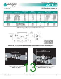
evaluation board layout in Figures 3 and 4.
2 · ΔILOAD
=
COUT
V
DROOP · fS
A laboratory test set-up typically consists of two long
wires running from the bench power supply to the eval-
uation board input voltage pins. The inductance of these
wires, along with the low-ESR ceramic input capacitor,
can create a high Q network that may affect converter
performance. This problem often becomes apparent in
the form of excessive ringing in the output voltage dur-
ing load transients. Errors in the loop phase and gain
measurements can also result.
In many practical designs, to get the required ESR, a
capacitor with much more capacitance than is needed
must be selected.
For both continuous or discontinuous inductor current
mode operation, the ESR of the COUT needed to limit the
ripple to ∆VO, V peak-to-peak is:
Since the inductance of a short PCB trace feeding the
input voltage is significantly lower than the power leads
from the bench power supply, most applications do not
exhibit this problem.
ΔVO
ESR ≤
ΔIL
Ripple current flowing through a capacitor’s ESR causes
power dissipation in the capacitor. This power dissipation
causes a temperature increase internal to the capacitor.
Excessive temperature can seriously shorten the expect-
ed life of a capacitor. Capacitors have ripple current rat-
ings that are dependent on ambient temperature and
should not be exceeded. The output capacitor ripple cur-
rent is the inductor current, IL, minus the output current,
IO. The RMS value of the ripple current flowing in the
output capacitance (continuous inductor current mode
operation) is given by:
In applications where the input power source lead induc-
tance cannot be reduced to a level that does not affect
the converter performance, a high ESR tantalum or alu-
minum electrolytic should be placed in parallel with the
low ESR, ESL bypass ceramic. This dampens the high Q
network and stabilizes the system.
Output Capacitor Selection
The function of output capacitance is to store energy to
attempt to maintain a constant voltage. The energy is
stored in the capacitor’s electric field due to the voltage
applied.
3
IRMS = ΔIL ·
= ΔIL · 0.289
6
The value of output capacitance is generally selected to
limit output voltage ripple to the level required by the
specification. Since the ripple current in the output induc-
tor is usually determined by L, VOUT and VIN, the series
impedance of the capacitor primarily determines the out-
put voltage ripple. The three elements of the capacitor
that contribute to its impedance (and output voltage
ESL can be a problem by causing ringing in the low
megahertz region but can be controlled by choosing low
ESL capacitors, limiting lead length (PCB and capacitor),
and replacing one large device with several smaller ones
connected in parallel.
w w w . a n a l o g i c t e c h . c o m
1145.2007.11.1.1
11

 ANALOGICTECH [ ADVANCED ANALOGIC TECHNOLOGIES ]