PRODUCT DATASHEET
AAT1145
SwitchRegTM
1.2A Step-Down Converter
Where ΔIL is inductor ripple current. Large value induc-
tors lower ripple current and small value inductors result
in high ripple currents. Choose inductor ripple current
approximately 30% of the maximum load current
1200mA, or
The worst case external current slope (m) using the
2.2μH inductor is when VOUT = 3.3V and is:
VOUT 3.3
=
m =
= 1.5A/µs
L
2.2
ΔIL = 360mA
To keep the power supply stable when the duty cycle is
above 50%, the internal slope compensation (mA)
should be:
For output voltages above 2.0V, when light-load effi-
ciency is important, the minimum recommended induc-
tor is 2.2μH.
1
ma ≥ · m = 0.75A/µs
Manufacturer’s specifications list both the inductor DC
current rating, which is a thermal limitation, and the
peak current rating, which is determined by the satura-
tion characteristics. The inductor should not show any
appreciable saturation under normal load conditions.
Some inductors may meet the peak and average current
ratings yet result in excessive losses due to a high DCR.
2
Therefore, to guarantee current loop stability, the slope
of the compensation ramp must be greater than one-half
of the down slope of the current waveform. So the inter-
nal slope compensated value of 1A/μs will guarantee
stability using a 2.2μH inductor value for all output volt-
ages from 0.6V to 3.3V.
Always consider the losses associated with the DCR and
its effect on the total converter efficiency when selecting
an inductor. For optimum voltage-positioning load tran-
sients, choose an inductor with DC series resistance in
the 20mΩ to 100mΩ range. For higher efficiency at
heavy loads (above 200mA), or minimal load regulation
(but some transient overshoot), the resistance should be
kept below 100mΩ. The DC current rating of the induc-
tor should be at least equal to the maximum load current
plus half the ripple current to prevent core saturation
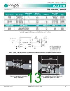
(1200mA + 360mA). Table 2 lists some typical surface
mount inductors that meet target applications for the
AAT1145.
Input Capacitor Selection
The input capacitor reduces the surge current drawn
from the input and switching noise from the device. The
input capacitor impedance at the switching frequency
should be less than the input source impedance to pre-
vent high frequency switching current passing to the
input. The calculated value varies with input voltage and
is a maximum when VIN is double the output voltage.
VO
⎛
VO ⎞
VIN
· 1 -
⎝
VIN
⎠
CIN =
For example, the 2.2ꢀH SD3118-2R2-R inductor selected
from Coiltronics has a 74mΩ DCR and a 2.00ADC current
rating. At full load, the inductor DC loss is 106mW which
gives a 5% loss in efficiency for a 1200mA, 1.8V output.
⎛ VPP
⎝ IO
⎞
- ESR ·fS
⎠
1
CIN(MIN)
=
⎛ VPP
⎝ IO
⎞
- ESR · 4 · fS
⎠
Slope Compensation
The AAT1145 step-down converter uses peak current
mode control with slope compensation for stability when
duty cycles are greater than 50%. The slope compensa-
tion is set to maintain stability with lower value inductors
which provide better overall efficiency. The output induc-
tor value must be selected so the inductor current down
slope meets the internal slope compensation require-
ments. As an example, the value of the slope compensa-
tion is set to 1A/μs which is large enough to guarantee
stability when using a 2.2μH inductor for all output volt-
age levels from 0.6V to 3.3V.
A low ESR input capacitor sized for maximum RMS cur-
rent must be used. Ceramic capacitors with X5R or X7R
dielectrics are highly recommended because of their low
ESR and small temperature coefficients. A 22μF ceram-
ic capacitor for most applications is sufficient. A large
value may be used for improved input voltage filtering.
The maximum input capacitor RMS current is:
VO
⎛
VO ⎞
IRMS = IO ·
· 1 -
⎝
VIN
VIN
⎠
w w w . a n a l o g i c t e c h . c o m
10
1145.2007.11.1.1

 ANALOGICTECH [ ADVANCED ANALOGIC TECHNOLOGIES ]