PRODUCT DATASHEET
AAT1145
SwitchRegTM
1.2A Step-Down Converter
delivers enhanced transient response for extreme pulsed
load applications. The addition of the feed forward
capacitor typically requires a larger output capacitor C2
for stability. The external resistor sets the output voltage
according to the following equation:
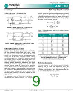
Applications Information
L1
VOUT
2.2μH
VIN 2.5V-5.5V
1.8V,1.2A
1
2
3
8
LX
LX
FB
EN
IN
7
5
C3
22pF
R1
C1
10μF
C2
634kΩ
AAT1145-0.6
22μF
AIN
10
9
6
⎛
R1⎞
R2⎠
R2
316kΩ
AGND
AGND
PGND
PGND
V
OUT = 0.6V · 1 +
4
⎝
⎛ V
OUT - 1 · R2
⎝ 0.6V
⎞
R1 =
⎠
Figure 1: Basic Application Circuit for the
Adjustable Output Version.
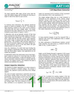
Table 1 shows the resistor selection for different output
voltage settings.
L1
2.2μH
VOUT
VIN 2.5V-5.5V
1.8V,1.2A
1
2
3
8
LX
LX
EN
IN
7
5
R2 = 59kΩ
R1 (kΩ)
R2 = 316kΩ
R1 (kΩ)
C1
10μF
C2
22μF
VOUT (V)
AAT1145-1.8
AIN
OUT
0.8
0.9
1.0
1.1
1.2
1.3
1.4
1.5
1.8
1.85
2.0
2.5
3.3
19.6
29.4
39.2
49.9
59.0
68.1
78.7
88.7
118
124
137
187
267
105
158
210
261
316
365
422
475
634
655
732
1000
1430
10
9
6
4
AGND
AGND
PGND
PGND
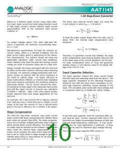
Figure 2: Basic Application Circuit for the Fixed
Output Versions.
Setting the Output Voltage
Figure 1 shows the basic application circuit with the
AAT1145 adjustable output version while Figure 2 shows
the application circuit with the AAT1145 fixed output
version. For applications requiring an adjustable output
voltage, the AAT1145-0.6 adjustable version can be
externally programmed. Resistors R1 and R2 in Figure 1
program the output to regulate at a voltage higher than
0.6V. To limit the bias current required for the external
feedback resistor string while maintaining good noise
immunity, the minimum suggested value for R2 is 59kΩ.
Although a larger value will further reduce quiescent
current, it will also increase the impedance of the feed-
back node, making it more sensitive to external noise
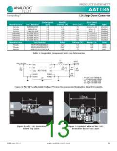
and interference. Table 1 summarizes the resistor values
for various output voltages with R2 set to either 59kΩ
for good noise immunity or 316kΩ for reduced no load
input current.
Table 1: Resistor Selections for Different Output
Voltage Settings (Standard 1% Resistors
Substituted For Calculated Values).
Inductor Selection
For most designs, the AAT1145 operates with inductor
values of 1μH to 4.7μH. Low inductance values are
physically smaller but require faster switching, which
results in some efficiency loss. The inductor value can
be derived from the following equation:
VOUT · (VIN - VOUT
)
L =
VIN · ΔIL · fOSC
The adjustable version of the AAT1145, combined with
an external feed forward capacitor (C3 in Figure 1),
w w w . a n a l o g i c t e c h . c o m
1145.2007.11.1.1
9

 ANALOGICTECH [ ADVANCED ANALOGIC TECHNOLOGIES ]