AS8221
Data Sheet - Detailed Description
8 Detailed Description
The AS8221 is a FlexRay Transceiver operating as an interface between the Communication Controller and the wired bus lines. The AS8221 is
designed to extend the application range for high speed and safety critical time triggered bus systems in an automotive environment. The drivers
are short circuit protected against the positive and negative supply voltage to increase the robustness and reliability of automotive systems. The
AS8221 operates at baudrates up to 10 Mbps.
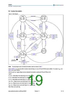
8.1 Block Description
The AS8221 consists of 9 functional blocks (see Figure 1):
Table 4. Functional Blocks
Functional Block
Short Description
Digital interface between the Transceiver and the host controller (HC)
The host interface comprises the read-out handler, which delivers failure and status information
via the ERRN pin to the host controller.
Host Controller Interface (HCI)
Digital interface between the Transceiver and the FlexRay communication controller (CC)
Communication Controller Interface (CCI)
Bus Guarding Interface (BGI)
Digital interface between the Transceiver and the FlexRay bus guardian (BG) or monitoring
circuitry.
The power supply interface consists of the voltage monitor (VM) with two analog inhibit outputs
switching external voltage supplies.
Power Supply Interface
(PSI)
The digital signals from the functional blocks of the device are fed into the internal logic where
the forwarding of FlexRay messages from analog side to digital interfaces and vice versa is
done. The state machine is embedded in the Internal Logic and the handling of error, wake, and
power-on flags is executed herein.
Internal Logic (IL)
The bus failure detector is directly connected to the bus pins, in order to detect several external
failure conditions which may occur on the bus.
The temperature protection turns off the output driver when reaching the specified internal
temperature in order to protect the device.
Bus Failure Detector (BFD)
Temperature Protection (TP)
The transmitter provides the differential signalling according the FlexRay standard on the bus
pins.
Transmitter
Receiver
The Receiver captures FlexRay valid signals at the bus pins and provides the received data
streams to the Internal Logic.
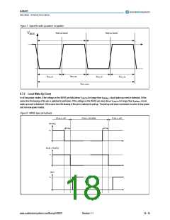
The wake-up detector recognizes valid wake-up frames on the bus, recognizes a wake signal
on the local WAKE pin and signals valid wake-up events to the Internal Logic.
Wake-Up Detector (WUD)
8.2 Events
Transitions in order to change between the operation modes are possible only if events are detected. The device supports three type of events,
events on the host controller interface (STBN, EN), detection of undervoltage or supply voltage recovery and wake events. Mode changes are
only performed upon detected events.
8.3 Operating Modes
The AS8221 provides the following operating modes:
ꢀ
ꢀ
ꢀ
ꢀ
ꢀ
NORMAL: non-low-power mode
RECEIVE-ONLY: non-low-power mode
STANDBY: low-power mode
GO-TO-SLEEP: low-power mode
SLEEP: low-power mode
www.austriamicrosystems.com/flexray/AS8221
Revision 1.1
15 - 43

 AMSCO [ AMS(艾迈斯) ]