18+0,1
(.709)
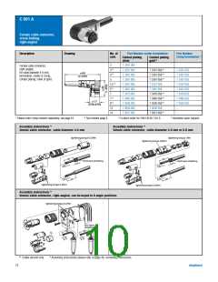
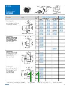
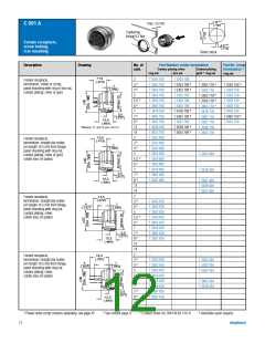
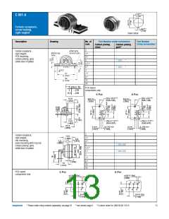
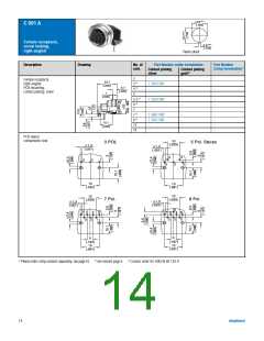
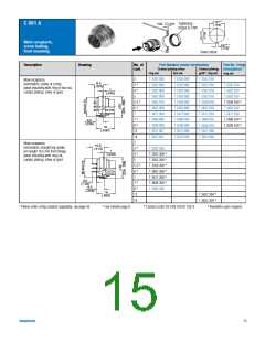
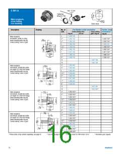
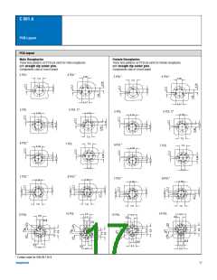
C 091 A
Female receptacle,
screw locking,
right-angled
2,8+0,1
(.110)
Panel cutout
Description
Drawing
No. of
cont.
Part Number solder termination
Part Number
Crimp termination1)
Contact plating
silver
Contact plating
gold2)
2
–
–
–
–
–
–
–
–
–
–
–
–
–
–
–
–
–
–
–
–
–
–
–
Female receptacle,
right-angled,
PCB mounting,
contact plating: gold,
solder area: tin plated.
3 3)
4 3)
5
–
–
T 3363 ... 3)
5 S 3)
6 3)
7
7 3)
8 3)
12
14
–
T 3403 ... 3)
–
–
–
–
–
3) *A Best.-Nr.
...218
PCB-layout
components side
3
8,3 ...228
5 Pol.
6 Pol.
+0,1
+0,1
(2x) 3,2
(DIA.126)
(2x) 3,2
0,2
0,2
12,8
8,5
(.335)
8,5
(.335)
(DIA.126)
(.504)
5
(.197)
+0,1
+0,1
(5x) 1,2
(6x) 1,2
12,5
(DIA.047)
(DIA.047)
(.492)
21,5
0,05
0,05
0,05
0,05
4
3,175
(.125)
4
3,175
(.125)
(.846)
(.157)
(.157)
2
–
–
–
–
–
–
–
–
–
–
–
–
–
–
–
–
–
–
–
–
–
–
–
Female receptacle,
right-angled,
rear mounting,
panel mounting with ring nut,
contact plating: gold,
solder area: tin plated.
12,5
3 3)
4 3)
5
–
(.484)
5,5
1,5
(.060)
(.217)
–
T 3363 902
5 S 3)
6 3)
7
7 3)
8 3)
12
14
–
T 3403 902
–
–
–
–
–
1
(.040)
13
(.512)
PCB-layout
components side
5 Pol.
6 Pol.
+0,1
+0,1
0,8 (5x)
0,8 (6x)
(.032)
(.032)
2
3
4
2
3
4
1
5
1
6
5
0,05
0,05
3
(2x)
3
(2x)
(.118)
(.118)
Amphenol
1) Please order crimp contacts separately, see page 43 2) see remark page 6 3) Contact order for DIN EN 60 130-9
13

 AMPHENOL [ Amphenol ]