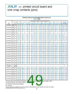
JT/LJT
how to order
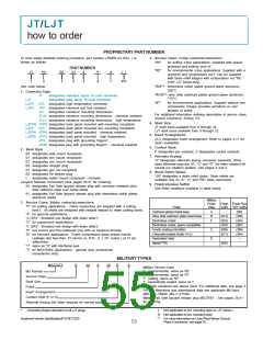
PROPRIETARY PART NUMBER
To more easily illustrate ordering procedure, part number JT00RE-22-2PA( ) is
shown as follows:
3. Service Class: Crimp contacts/connectors:
“RP”
“RE”
for potting crimp applications. Supplied with spacer
grommet and potting boot.††
for environmental crimp applications. Supplied with a
grommet and compression nut.† Can be supplied
with strain relief integral with compression nut “RE
(SR)”. (JT Series only).
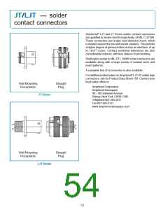
PART NUMBER
JT
1
00
2
RE
3
-
22
-
2
P
6
A
7
( )
4
5
8/9
See code below:
“RGF”* electroless nickel plated ground plane aluminum,
200°C
1. Connector Type:
“RGW”** olive drab cadmium plated ground plane aluminum,
175°C
JT
designates standard Junior Tri-Lock connector
designates long Junior Tri-Lock connector
LJT
LJTS
LJTN
“RT”
for environmental applications. Supplied without rear
accessories. Design provides serrations on rear
threads of shells.
JTS designates high temperature connector
JTN designates chemical and fuel resistant
JTL
JTLN designates miniature mounting dimensions - chemical resistant
JTLS designates miniature mounting dimensions - high temperature
designates miniature mounting dimensions
For additional information defining description of service class,
consult Amphenol, Sidney, NY.
4. Shell Size:
LJTPQ JTPQ designates back panel mounted wall mounting receptacle
LJTP JTP designates back panel mounted box mounting receptacle
LJTPN JTPN designates back panel mounted - chemical resistant
LJTPS JTPS designates back panel mounted - high temperature
JTG designates plug with grounding fingers*
JT shell sizes available from 8 through 24.
LJT shell sizes available from 9 through 25.
5. Insert Arrangement:
22-2 designates insert arrangement. Refer to pages 4-11 for
insert availability.
JTNG designates plug with grounding fingers* - chemical resistant
6. Contact Style:
2. Shell Style
P designates pin contacts; S designates socket contacts.
00 designates wall mount receptacle
01 designates line mount receptacle
02 designates box mount receptacle
06 designates straight plug
07 designates jam nut receptacle
08 designates 90 degree plug
7. Alternate Keying:
“A” designates alternate keying connector assembly. Other
basic alternate keys are “B”, “C” and “D”. No letter required for
normal (no rotation) position. See pages 4 and 5.
8. Strain Relief Option:
“SR” designates a strain relief clamp. Strain reliefs are
available only on “A”, “C” and “RE” class connectors.
I
designates solder mount receptacle - hermetic
Lanyard Release Connectors (See pages 38-41 for ordering)
88 designates Fail Safe lanyard release plug with corrosion resistant olive
drab cadmium plate over nickel shells
9. Finish Variation Suffix:
See finish variations available in table below:
91 designates Fail Safe lanyard release plug with electroless nickel plated
aluminum shells.
Military
Finish
Data
3. Service Class: Solder contacts/connectors:
Finish Finish Plus
Suffix “SR” Suffix
“P” for potting applications - These connectors are supplied with a potting
boot.† All shells are designed with integral featues to retain potting boots.
“A” for general applications.
“A (SR)” - threaded rear design with strain relief.†
“C” for pressurized applications
Finish
Cadmium plated nickel base
Olive drab cadmium plate nickel base
Electroless nickel
A
B
F
(SR)
(014)
(023)
(453)
(005)
(011)
–
(386)
(424)
(467)
(300)
(344)
–
Electroless nickel, space compatible
Anodic coating (Alumilite)
Chromate treated (Iridite 14-2)
Passivated steel
“C (SR)” - threaded rear design with strain relief.†
“E” box mount and thru-bulkhead only with no backend threads.
“H” for hermetic applications - Fused compression glass sealed inserts.
Leakage rate less than .01 micron cu. ft./hr. (1 x 10⁻⁷ cc/sec.) at 15 psi
differential.
C
E
Nickel-PTFE
(038)
“Y” same as “H” with interfacial seal.
“T” for MS27599A applications - general duty, pressurized
(receptacles only)
MILITARY TYPES
MS27473
E
14
A
18
P
A
Military Service Class
E
T
P
Y
environmental, same as RE
environmental, same as RT
potting, same as RP
MS Number
Service Class
Shell Size
Finish
hermetically sealed, same as Y
For finish variations see above chart. For additional data, see page 3.
For MS depictions and dimensional data see applicable Mil-Spec.
(MIL-DTL-38999, MIL-C-27599).
Military Fail Safe lanyard release plug MS27661 - See pages 38-41
for ordering.
Insert Arrangement
Contact Style (P or S)
Alternate Keying (No letter required for normal position)
*
Grounding fingers standard on all LJT plugs
†
Not applicable to box mounting style or LJT Series I.
†† Not applicable to box mounting style.
** For more information on Coax/Triax/Twinax Ground
Plane Connectors, see page 55.
AmphenolVendor Identification/FSCM 77820
53

 AMPHENOL [ Amphenol ]