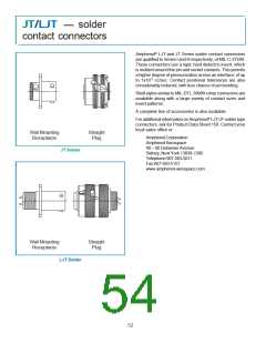
JT/LJ T – acce s s orie s
universal “header assembly” for flex print or
PC board mounting
Mounts to all MIL-DTL-38999 and
MIL-C-26482 Connectors
The use of connectors with printed circuit
termination is rapidly gaining popularity due
to the rise of high volume, vapor phase or
wave solder manufacturing processes. Ter-
mination of this style of connector to flex print
or a printed circuit board represents a major
cost in the manufacturing process for users.
When adding flex or printed circuit board
assemblies to an expensive filter or filter/
transient protection connector, the total cost
of a failed solder joint, a bent pin, or an un-
anticipated electrical failure becomes prohibitive. The universal header as-
sembly from Amphenol will provide for easy separation of the connector from
the board on these occasions.
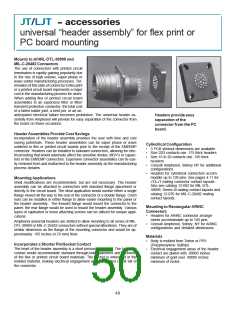
Headers provide easy
separation of the
connector from the PC
board.
Header Assemblies Provide Cost Savings
Incorporation of the header assembly provides the user with time and cost
saving potentials. These header assemblies can be vapor phase or wave
soldered to flex or printed circuit boards prior to the receipt of the EMI/EMP
connector. Headers can be installed to standard connectors, allowing for elec-
trical testing that would adversely affect the sensitive diodes, MOV’s or capaci-
tors in the EMI/EMP connectors. Expensive connector assemblies can be eas-
ily removed from and reattached to the header assembly as the manufacturing
process dictates.
Cylindrical Configuration
•
•
•
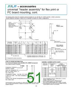
3 PCB stickout dimensions are available.
Size 22D contacts use .175 thick headers
Size 16 to 20 contacts use .195 thick
headers
•
•
Consult Amphenol, Sidney NY for additional
configurations.
Headers for cylindrical connectors accom-
modate up to 128 pins. See pages 4-11 for
JT/LJT mating connector contact layouts.
Also see catalog 12-092 for MIL-DTL-
38999, Series III mating contact layouts and
catalog 12-070 for MIL-C-26482 mating
contact layouts.
Mounting Applications
Shell modifications are recommended, but are not necessary. The header
assembly can be attached to connectors with standard flange placement or
directly to the circuit board. The ideal application would involve either a single
flange moved all the way to the rear of the connector or a double flange. Cinch
nuts can be installed in either flange to allow easier mounting to the panel or
the header assembly. The forward flange would mount the connector to the
panel; the rear flange would be used to mount the header assembly. Various
types of captivated or loose attaching screws can be utilized for unique appli-
cations.
Mounting to Rectangular ARINC
Connectors
•
Headers for ARINC connector arrange-
ments accommodate up to 150 pins
Consult Amphenol, Sidney, NY for ARINC
configurations and detailed dimensions.
Amphenol universal headers are slotted to allow mounting to all series of MIL-
DTL-38999 or MIL-C-26482 connectors without special alterations. They are of
similar dimension as the flange of the mounting connector and would be ap-
proximately .185 inches (4.70 mm) thick.
•
Materials
•
Body is molded from Torlon or PPS
(Polyphenylene Sulfide)
Incorporates a Shorter Pin/Socket Contact
The heart of the header assembly is a short pin/socket contact. The tail of the
contact would accommodate standard through-hole diameters and thickness
of the flex or printed circuit board materials. The socket is imbedded in the
molded material, making electrical engagement with the printed circuit tail of
the connector.
•
Electrical engagement areas of the header
contact are plated with .00003 inches
minimum of gold over .00005 inches
minimum of nickel.
48

 AMPHENOL [ Amphenol ]