LJ T Bre akaway Fail Safe
lanyard release plug
how to order, cont.
HOW TO ORDER - BY MILITARY PART NUMBER
HOW TO ORDER - BY PROPRIETARY PART NUMBER
FAIL SAFE 88-5388 OR 91-5388
FAIL SAFE MS27661
MS27661
T
17
B
35 P A
88
–
5388
29
–
40
P
MS Number
Finish
Service Class
Shell Size
Connector Type Identification
Shell Size and Insert
Arrangement Code
Finish
Lanyard Length Code
Insert Arrangement
Contact Style
Polarizing Position
Contact Type/Alternate Insert Rotation
Finish
88 designates corrosion resistant olive drab cadmium
plate over nickel, 500 hour extended salt spray,
EMI –50dB @ 10 GHz specification min., 175°C
MS Number
MS Number designates MIL-DTL-38999, Series I
LJT Lanyard Release Plug
91 designates electroless nickel plated aluminum,
optimum EMI shielding effectiveness –65dB @ 10 GHz
specification min., 48 hour salt spray, 200°C
These are standard finishes. Consult Amphenol Aerospace,
Sidney, NY for variations.
Service Class
E for environmental crimp applications (inactive for new
design)
T for environmental crimp applications with serrations on
rear threads of shell
Connector Type Identification
Shell Size
88/91-5388 designates MIL-DTL-38999, Series I LJT Lanyard
Release Plug
MIL-DTL-38999, sizes 11 through 25
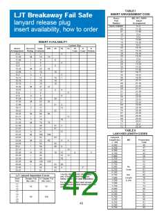
Shell Size and Insert Arrangement Code
Finish
Shell sizes are MIL-DTL-38999, Series III from 11 thru 25. The
basic part number selected specifies the insert arrangement.
See Table I (page 40) for coded part number that correlates to
insert arrangement.
B designates corrosion resistant olive drab cadmium
plated aluminum, 500 hour extended salt spray,
EMI shielding effectiveness –50dB @ 10 GHz
specification min., 175°C
F designates electroless nickel plated aluminum,
48 hour salt spray, EMI shielding effectiveness –65dB
@
Lanyard Length Code
See Table II (page 40) for lanyard length code number.
10 GHz500 specification min., 200°C
These are standard finishes. Consult Amphenol Aerospace
for variations.
Contact Type/Alternate Rotations
P designates pin, S designates socket for normal positioning
of contacts. When an alternate position of the connector is
required to prevent cross-mating, a different letter (other than
P or S) is used. See alternate positioning for LJT on page 5,
then convert to Amphenol proprietary coding by the following
chart.
Insert Arrangement
MIL-DTL-38999, see insert identification chart on page 40.
Contact Style
P designates Lanyard Release plug with pin contacts
S designates Lanyard Release plug with socket contacts
Pin Contacts
Socket Contacts
MS Letter
Amphenol Letter MS Letter Amphenol Letter
Polarizing Postion
P
P (normal)
S
S (normal)
For alternate positions of connector (to prevent cross-
mating) see LJT key/keyway rotation description on page
5. (No letter is required for normal).
PA
PB
PC
PD
E
R
W
Y
SA
SB
SC
SD
F
T
X
Z
41

 AMPHENOL [ Amphenol ]