AME
1.5MHz, 600mA
Synchronous Buck Converter
AME5248A
Output Capacitor Selection
Thermal Considerations
The selection of COUT is driven by the required effective
series resistance (ESR). Typically, once the ESR re-
quirement for COUT has been met, the RMS current rating
generally far exceeds the IRIPPLE(P-P) requirement. The
output ripple VOUT is determined by
In most applications the AME5248A does not dissi-
pate much heat due to its high efficiency. But, in applica-
tions where the AME5248A is running at high ambient
temperature with low supply voltage and high duty cycles,
such as in dropout, the heat dissipated may exceed the
maximum junction temperature of the part. If the junc-
tion temperature reaches approximately 160℃, both
power switches will be turned off and the SW node will
become high impedance. To avoid the AME5248A from
exceeding the maximum junction temperature, the user
will need to do some thermal analysis. The goal of the
thermal analysis is to determine whether the power dis-
sipated exceeds the maximum junction temperature of
the part. The temperature rise is given by:
1
DVOUT » DIL (ESR+
)
8COUT fSW
Where fSW=operating frequency, COUT=output capaci-
tance and △IL=ripple current in the inductor. For a fixed
output voltage, the output ripple is highest at maximum
input voltage since △IL increases with input voltage.
At the light load current, the device operates in Power
Saving Mode, and the output voltage ripple is indepen-
dent of the value of the output capacitor. The output ripple
is set by the internal comparator thresholds and is also
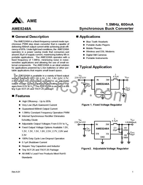
affected by the feedback capacitor C1 in figure2. Large
capacitor values can decrease the output ripple, usually
a 22pF capacitor is sufficient for most applications.
TR = (PD)´ qJA
Where PD is the power dissipated by the regulator and
qJA is the thermal resistance from the junction of the die
to the ambient temperature.
When the input and output ceramic capacitors are cho-
sen, choose the X5R or X7R dielectric formulations. These
dielectrics have the best temperature and voltage char-
acters have the best temperature and voltage character-
istics of all the ceramics for a given value and size.
Output Voltage Setting
In the adjustable version, the output voltage is set by a
resistor divider according to following formula:
R2
VOUT = 0.5V ´ (1+
)
R1
The external resistor divider is connected to the output.
Rev.A.01
11

 AME [ ANALOG MICROELECTRONICS ]