AME
1.5MHz, 600mA
Synchronous Buck Converter
AME5248A
nApplication Information
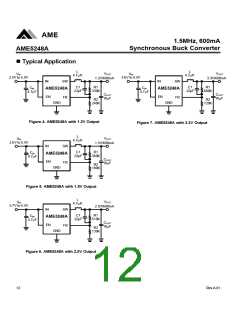
The typical AME5248A application circuit is shown in
Figure1. The external component selection is driven by
the load requirement.
Toroid or shielded pot cores in ferrite or permalloy ma-
terials are small and don't radiate energy but generally
cost more than powdered iron core inductors with similar
characteristics. The choice of which style inductor to use
mainly depends on the price vs. size requirements and
any radiated field/EMI requirements.
Inductor Selection
Although the inductor does not influence the operating
frequency, the inductor value has a direct effect on ripple
current. The inductor ripple current △IL decreases with
Input Capacitor Selection
higher inductance and increases with higher VIN or VOUT
:
In continuous mode, the source current of the main
power MOSFET is a square wave of duty cycle VOUT/VIN.
To prevent large voltage transients, a low ESR input ca-
pacitor sized for the maximum RMS current must be used.
The input filter capacitor supplies current to the main power
MOSFET of AME5248A in the first half of each cycle and
reduces voltage ripple imposed on the input power source.
A ceramic capacitor's low ESR provides the best noise
filtering of input voltage spikes due to this rapidly chang-
ing current. Select a capacitor with sufficient ripple cur-
rent rating.
VIN - VOUT VOUT
DIL =
´
L´ fSW
VIN
The inductor must have a saturation (incremental) cur-
rent rating equal to the peak switch-current limit. For high
efficiency, minimize the inductor's DC resistance.
The inductor value also has an effect on Power Saving
Mode operation. Lower inductor values (higher ripple cur-
rent) will cause the transition from PWM to Power Saving
Mode to occur at lower load currents, which can cause a
dip in efficiency in the upper range of low current opera-
tion.
The input capacitor's maximum RMS capacitor current
is given by:
(VIN - VOUT )VOUT
IRMS » IMAX
VIN
Inductor Core Selection
Once the value for L is known, the type of inductor
must be selected. High efficiency converters generally
cannot afford the core loss found in low cost powdered
iron cores, forcing the use of more expensive ferrite or
mollypermalloy cores. Actual core loss is independent of
core size for a fixed inductor value but it is very depen-
dent on the inductance selected. As the inductance in-
creases, core losses decrease. Unfortunately, increased
inductance requires more turns of wire and therefore cop-
per losses will increase. Ferrite designs have very low
core losses and are preferred at high switching frequen-
cies, so design goals can concentrate on copper loss
and preventing saturation. Ferrite core material saturates
"hard", which means that inductance collapses abruptly
when the peak design current is exceeded. This result in
an abrupt increase in inductor ripple current and conse-
quent output voltage ripple. Do not allow the core to satu-
rate! Different core materials and shapes will change the
size/current and price/current relationship of an inductor.
Where the maximum average output current IMAX equals
the peak current I minus half peak-to-peak ripple cur-
LIM
rent, IMAX=ILIM-△IL/2.
This formula has a maximum at VIN=2VOUT, where I
RMS
=IOUT/2. This simple worst-case condition is commonly
used for design because even significant deviations do
not offer much relief. Note that ripple current ratings from
capacitor manufacturers are often based on only 2000
hours of life which makes it advisable to further derate the
capacitor, or choose a capacitor rated at a higher tem-
perature than required. Several capacitors may also be
paralleled to meet size or height requirements in the de-
sign.
10
Rev.A.01

 AME [ ANALOG MICROELECTRONICS ]