AME, Inc.
High-Efficiency, 30V Boost
Converters for 2 to 6 White LEDs
AME5134
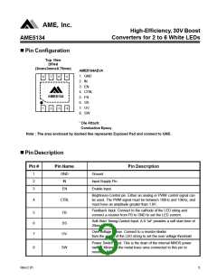
n Pin Configuration
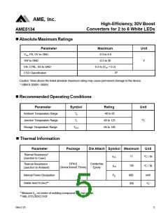
Top View
DFN-8
(3mmx3mmx0.75mm)
AME5134AEVA
1. GND
2. IN
8
7
6
5
3. EN
4. CTRL
5. FB
AME5134
6. SS
7. OV
1
2
3
4
8. SW
* Die Attach:
Conductive Epoxy
Note : The area enclosed by dashed line represents Exposed Pad and connect to GND.
n Pin Description
Pin #
Pin Name
Pin Description
1
2
3
GND
IN
Ground
Input-Supply Pin.
Enable Input.
EN
Brightness-Control pin. Either an analog or PWM control signal can
be used. The PWM signal must be between 100Hz and 10kHz, and
must have an amplitude greater than 1.8V.
4
CTRL
Feedback Input. Connect to the cathode of the LED string and
connect a resistor from FB to GND to set the LED current.
5
6
7
FB
SS
OV
Soft-Start Timing-Control Input. A 0.1uF provides a soft start time of
20ms.
Over voltage Sense. Connect to a resistor-divider
from the anode of the LED string to set the over voltage threshold.
Power Switch input. This is the drain of the internal NMOS power
switch. Minimize the metal trace area connected to this pin to
minimize EMI.
8
SW
Rev.C.01
3

 AME [ ANALOG MICROELECTRONICS ]