Revision 1.02 – April 12, 2007
S5920 – PCI Product: Pass-Thru Operation
S5920 PASSIVE MODE OPERATION
Data Book
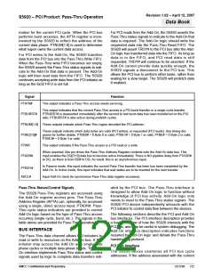
PTBE[3:0]# 0h. Indicates the Pass-Thru access has all
bytes valid.
The Pass-Thru address and data registers can be
accessed as Add-On operation registers. The Pass-
Thru FIFO is updated on the rising edge of ADCLK.
For this reason, all Pass-Thru inputs must be synchro-
nous to ADCLK. In the following sections the Add-On
Pass-Thru interface is described for Pass-Thru single
cycle accesses, burst accesses, target-requested
retries, and when using 8-bit and 16-bit Add-On data
buses.
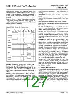
Clock 2: SELECT#, ADR[6:2] and BE[3:0]# inputs are
driven to read the Pass-Thru Write FIFO at offset 2Ch.
DQ[31:0] is driven one clock after RD# and SELECT#
are asserted. PTRDY# is asserted, indicating that the
transfer is complete.
Clock 3: PTBE[3:0] will update one clock after RD# is
asserted to indicate which bytes have not yet been
read. The data is also driven on the DQ bus since RD#
was asserted a clock earlier. Since PTRDY# was sam-
pled asserted, PTATN# is deasserted and the Pass-
Thru access is complete. If the Add-On logic requires
more time to complete the read, PTRDY# can be
delayed, extending the Pass-Thru cycle.
Single-Cycle PCI to Pass-Thru Write
A single-cycle Pass-Thru write operation occurs when
a PCI initiator writes a single value to the Pass-Thru
region. PCI single cycle transfers consist of an
address phase followed by one data phase. During the
address phase of the PCI transfer, the S5920 stores
the PCI address into the Pass-Thru Address Register
(APTA). If the S5920 determines that the address is
within one of its defined Pass-Thru regions, it captures
the PCI data into the FIFO.
Clock 4: As PTATN# is deasserted, the Pass-Thru
access is complete, and the S5920 can accept new
Pass-Thru accesses starting on the next clock. The
other Pass-Thru signals can also change state (in
anticipation of a new transfer). The S5920 stops driv-
ing the DQ bus as RD# and SELECT# were not valid
on the previous cycle.
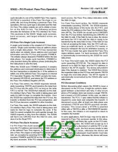
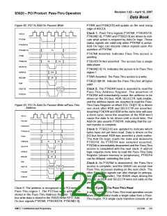
Figure 4 shows a single cycle Pass-Thru write access
in the Passive Mode. The Add-On must read the data
stored in the FIFO and transfer it to its destination. If
the proper SELECT#, ADR[6:2] and BE[3:0]# signals
are present, the S5920 will drive data one clock after
RD# is asserted. It will stop driving data after the rising
edge of ADCLK when RD# has been sampled
deasserted.
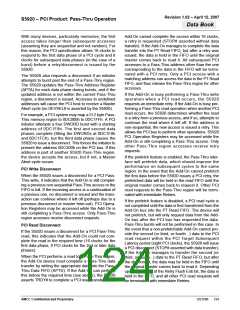
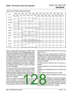
Figure 5 shows a single cycle Pass-Thru write for the
Passive Mode using the Pass-Thru address informa-
tion. This provides PCI cycle address information to
select a specific address location within an Add-On
memory or peripheral. Add-On logic may latch the
address for use during the data transfer (if PTADR#
was asserted). Typically, the entire 32-bit address is
not required. The Add-On may implement a scheme
where only the required number of address bits are
latched. It may also be useful to use the Pass-Thru
region identifiers, PTNUM[1:0], as address lines. For
example, Pass-Thru region 1 might be a 64K block of
SRAM for data, while Pass-Thru region 2 might be
64K of SRAM for code storage (downloaded from the
host during initialization). Using PTNUM0 as address
line A16 allows two unique add-on memory regions to
be defined.
Clock 0: The PCI bus cycle address information is
stored in the S5920 and later stored in the Pass-Thru
Address Register. The PCI address is recognized as a
write to Pass-Thru region 1. The PCI data is stored in
the S5920 Write FIFO.
Clock 1: Pass-Thru signals PTATN#, PTBURST#,
PTNUM[1:0], PTWR and PTBE[3:0] are driven to indi-
cate what action is required by Add-On logic. These
status signals are valid only when PTATN# is active.
Add-On logic can decode status signals upon the
assertion of PTATN#.
Unlike all other Add-On operation register reads, the
Add-On PTADR# input directly accesses the Pass-
Thru Address Register and drives the contents onto
the data bus during the same clock cycle. WR# must
not be asserted the same time as PTADR#, or there
would be contention on the DQ bus! However, it is per-
mitted to assert RD# and PTADR# during the same
cycle. This is because all reads performed with RD#
are pipelined, while address reads with PTADR# are
not pipelined.
PTATN# Asserted. Indicates a Pass-Thru access is
pending
PTBURST# Deasserted. The access has a single data
phase.
PTNUM[1:0] 1h. Indicates the access is to Pass-Thru
region 1.
PTWR Asserted. The Pass-Thru access is a write.
AMCC Confidential and Proprietary
DS1596
125

 AMCC [ APPLIED MICRO CIRCUITS CORPORATION ]