2–26
Chapter 2: MAX II Architecture
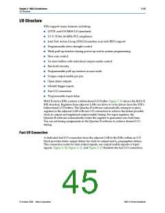
I/O Structure
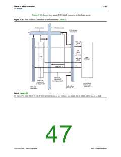
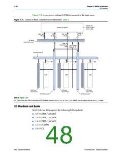
Figure 2–21 shows how a column I/O block connects to the logic array.
Figure 2–21. Column I/O Block Connection to the Interconnect (Note 1)
Column I/O
Block Contains
Up To 4 IOEs
Column I/O Block
data_in
[3..0]
data_out
[3..0]
OE
[3..0]
fast_out
[3..0]
4
4
4
4
I/O Block
Local Interconnect
Fast I/O
Interconnect
Path
LAB Column
Clock [3..0]
R4 Interconnects
LAB
LAB
LAB
LAB Local
Interconnect
LAB Local
Interconnect
LAB Local
Interconnect
C4 Interconnects
C4 Interconnects
Note to Figure 2–21:
(1) Each of the four IOEs in the column I/O block can have one data_outor fast_outoutput, one OEoutput, and one data_ininput.
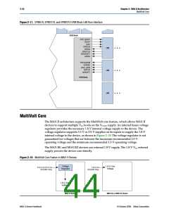
I/O Standards and Banks
MAX II device IOEs support the following I/O standards:
■
■
■
■
■
3.3-V LVTTL/LVCMOS
2.5-V LVTTL/LVCMOS
1.8-V LVTTL/LVCMOS
1.5-V LVCMOS
3.3-V PCI
MAX II Device Handbook
© October 2008 Altera Corporation

 ALTERA [ ALTERA CORPORATION ]