Chapter 2: MAX II Architecture
2–9
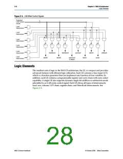
Logic Elements
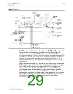
Normal Mode
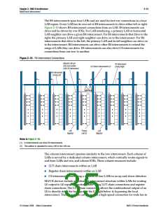
The normal mode is suitable for general logic applications and combinational
functions. In normal mode, four data inputs from the LAB local interconnect are
inputs to a four-input LUT (see Figure 2–7). The Quartus II Compiler automatically
selects the carry-in or the data3 signal as one of the inputs to the LUT. Each LE can use
LUT chain connections to drive its combinational output directly to the next LE in the
LAB. Asynchronous load data for the register comes from the data3 input of the LE.
LEs in normal mode support packed registers.
Figure 2–7. LE in Normal Mode
sload
sclear
aload
(LAB Wide) (LAB Wide)
(LAB Wide)
Register chain
connection
addnsub (LAB Wide)
ALD/PRE
(1)
Row, column, and
ADATA
D
Q
DirectLink routing
data1
data2
Row, column, and
DirectLink routing
ENA
CLRN
data3
cin (from cout
of previous LE)
4-Input
LUT
clock (LAB Wide)
Local routing
data4
ena (LAB Wide)
aclr (LAB Wide)
LUT chain
connection
Register
chain output
Register Feedback
Note to Figure 2–7:
(1) This signal is only allowed in normal mode if the LE is at the end of an adder/subtractor chain.
Dynamic Arithmetic Mode
The dynamic arithmetic mode is ideal for implementing adders, counters,
accumulators, wide parity functions, and comparators. An LE in dynamic arithmetic
mode uses four 2-input LUTs configurable as a dynamic adder/subtractor. The first
two 2-input LUTs compute two summations based on a possible carry-in of 1 or 0; the
other two LUTs generate carry outputs for the two chains of the carry-select circuitry.
As shown in Figure 2–8, the LAB carry-in signal selects either the carry-in0or
carry-in1 chain. The selected chain’s logic level in turn determines which parallel sum
is generated as a combinational or registered output. For example, when
implementing an adder, the sum output is the selection of two possible calculated
sums:
data1 + data2 + carry in0
or
data1 + data2 + carry-in1
© October 2008 Altera Corporation
MAX II Device Handbook

 ALTERA [ ALTERA CORPORATION ]