Off-Line Quasi-Resonant Switching Regulators
STR-X6757
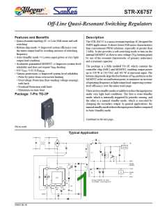
Description (continued)
Thesoft-startmodeminimizessurgevoltageandreducespowerstress
to the MOSFET and to the secondary rectifying diodes during the
start-upsequence.Variousprotectionssuchasovervoltage,overload,
overcurrent, maximum on-time protections and avalanche-energy-
guaranteed MOSFET secure good system-level reliability.
Applications include the following:
▪ Set Top Box
▪ LCD PC monitor, LCD TV
▪ Printer, Scanner
▪ SMPS power supplies
Selection Guide
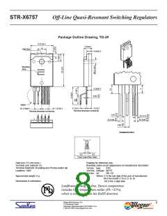
Part Number
Package
STR-X6757
TO-3P
Absolute Maximum Ratings at TA = 25°C
Parameter
Symbol
IDpeak Single pulse
Conditions
Rating
18
Unit
A
Drain Current1
Maximum Switching Current2
Single Pulse Avalanche Energy3
Input Voltage for Controller (MIC)
SS/OLP Terminal Voltage
FB Terminal Inflow Current
FB Terminal Voltage
IDmax
EAS
VCC
VSSOLP
IFB
VFB
TA = –20°C to 125°C
Single pulse, VDD = 30 V, L = 50 mH, ILpeak = 3.53 A
18
326
35
A
mJ
V
V
mA
V
–0.5 to 6.0
10
–0.5 to 9.0
–1.5 to 5.0
44
2.8
0.8
–20 to 125
–20 to 125
–40 to 125
150
IFB within the limits of IFB
OCP/BD Terminal Voltage
VOCPBD
V
With infinite heatsink
Without heatsink
VCC × ICC
W
W
W
°C
°C
°C
°C
MOSFET Power Dissipation4
PD1
Controller (MIC) Power Dissipation
Operating Internal Leadframe Temperature
Operating Ambient Temperature
Storage Temperature
Channel Temperature
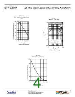
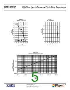
1Refer to MOSFET ASO curve
2IDMAX is the drain current determined by the drive voltage of the IC and the threshold voltage, Vth, of the MOSFET
3Refer to Avalanche Energy Derating curve
4Refer to MOSFET Ta-PD1 curve
PD2
TF
TOP
Recommended operation temperature, see cautions
T
stg
T
ch
All performance characteristics given are typical values for circuit or
system baseline design only and are at the nominal operating voltage and
an ambient temperature, TA, of 25°C, unless otherwise stated.
Allegro MicroSystems, Inc.
115 Northeast Cutoff
2
Worcester, Massachusetts 01615-0036 U.S.A.
1.508.853.5000; www.allegromicro.com

 ALLEGRO [ ALLEGRO MICROSYSTEMS ]