ATS672LSB
SELF-CALIBRATING TPOS GEAR-TOOTH SENSOR WITH 9-BIT SIGNAL CAPTURE
Preliminary – Subject to Change
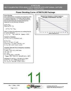
Power Derating Curve: ATS672LSB Package
Power Derating
Maximum Power Dissipation vs. Ambient Temperature
Due to internal power consumption, the temperature of the
SB Package: Thermal Resistance: 150°C/Watt
1000
IC (junction temperature, Tj) is higher than the ambient
900
environment temperature, Ta. To ensure that the device
800
does not operate above the maximum rated junction
700
temperature use the following calculations:
600
500
∆T=PD * RθJA
400
Where PD=Vcc * Icc
300
200
∴ ∆T=Vcc * Icc * RθJA
100
0
Where ∆T denotes the temperature rise resulting from the
20
30
40
50
60
70
80
90 100 110 120 130 140 150 160 170
IC’s power dissipation:
Ambient Temperature [°C]
TJ = TA + ∆T
RθJA =150°C/W TJ(max) = 170°C
Typical TJ Calculation:
TA =25°C, Vcc=5 V, Icc(On)=6.5 mA
PD=Vcc * Icc
PD= 5 V * 6.5 mA = 32.5 mW
∆T=PD* RθJA = 32.5 mW * 150°C/W = 4.9°
TJ = TA + ∆T = 25°C + 4.9°C = 29.9°C
Maximum Allowable Power Dissipation Calculation
TJ = TA + ∆T
TJ (max) = 170°C, if TA=160°C then:
170 = 160 + ∆T
∆T = 10°C
∆T = PD* RθJA (RθJA = 150°C/W)
∴ PD(max) = 10°C / 150°C/W = 66.6 mW @ TA = 160°C
Maximum Vcc for PD(max) =111 mW at TA=160°C
PD=Vcc * Icc Icc = 10 mA (max) at 160°C
Vcc = PD / Icc = 66.6 mW / 10 mA = 6.66 V
Rev. 1.2 May 1, 2002
115 Northeast Cutoff, Box 15036
Worcester, Massachusetts 01615-0036 (508) 853-5000
Copyright © 1993, 1995 Allegro MicroSystems, Inc.
Page 11 of 12

 ALLEGRO [ ALLEGRO MICROSYSTEMS ]