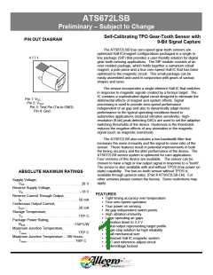
ATS672LSB
SELF-CALIBRATING TPOS GEAR-TOOTH SENSOR WITH 9-BIT SIGNAL CAPTURE
Preliminary – Subject to Change
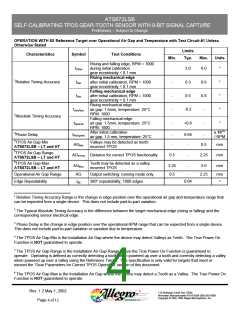
OPERATION WITH 8X Reference Target over Operational Air Gap and Temperature with Test Circuit #1 Unless
Otherwise Stated
Limits
Characteristics
Symbol
Test Conditions
Min.
Typ.
Max.
Units
Rising and falling edge, RPM = 1000
during initial calibration
tICRel
3.0
6.0
°
gear eccentricity < 0.1 mm
Rising mechanical edge
after initial calibration, RPM = 1000
gear eccentricity < 0.1 mm
Falling mechanical edge
after initial calibration, RPM = 1000
gear eccentricity < 0.1 mm
Rising mechanical edge
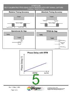
1Relative Timing Accuracy
tRel
-
-
-
-
0.3
0.5
0.6
0.8
-
°
°
°
°
tRel
tAbsRise
air gap: 1.5mm, temperature: 25°C
RPM: 1000
-0.2
+0.6
2Absolute Timing Accuracy
3Phase Delay
Falling mechanical edge
tAbsFall
air gap: 1.5mm, temperature: 25°C
RPM: 1000
-
After initial calibration
x 10-5°
tRelSpeed
AGMin
-
-
6.66
-
-
air gap: 1.5 mm, temperature: 25°C
/ RPM
4TPOS Air Gap Min
Valleys may be detected as teeth:
0.5
mm
mm
mm
ATS672LSB – LT and HT
incorrect TPOS
5TPOS Air Gap Range
AGTPOS Distance for correct TPOS functionality
0.5
-
-
2.25
ATS672LSB – LT and HT
6TPOS Air Gap Max
Teeth may be detected as a valley:
AGMax
2.25
0.5
5.0
ATS672LSB – LT and HT
incorrect TPOS
Operational Air Gap Range
AG
tθE
Output switching: running mode only
360° repeatability, 1000 edges
-
2.25
mm
Edge Repeatability
0.04
°
1 Relative Timing Accuracy Range is the change in edge position over the operational air gap and temperature range that
can be expected from a single device. This does not include part-to-part variation.
2 The Typical Absolute Timing Accuracy is the difference between the target mechanical edge (rising or falling) and the
corresponding sensor electrical edge.
3 Phase Delay is the change in edge position over the operational RPM range that can be expected from a single device.
This does not include part-to-part variation or variation due to temperature.
4 The TPOS Air Gap Min is the Installation Air Gap where the device may detect Valleys as Teeth. The True Power On
Function is NOT guaranteed to operate.
5 The TPOS Air Gap Range is the Installation Air Gap Range where the True Power On Function is guaranteed to
operate. Operating is defined as correctly detecting a tooth when powered up over a tooth and correctly detecting a valley
when powered up over a valley using the Reference Target. This specification is only valid for targets that meet or
exceed the ‘Gear Parameters for Correct TPOS Operation’ section of this document.
6 The TPOS Air Gap Max is the Installation Air Gap where the device may detect a Tooth as a Valley. The True Power On
Function is NOT guaranteed to operate.
Rev. 1.2 May 1, 2002
115 Northeast Cutoff, Box 15036
Worcester, Massachusetts 01615-0036 (508) 853-5000
Copyright © 1993, 1995 Allegro MicroSystems, Inc.
Page 4 of 12

 ALLEGRO [ ALLEGRO MICROSYSTEMS ]