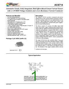
Automotive Grade, Fully Integrated, Hall Effect-Based Linear Current Sensor
with 2.1 kVRMS Voltage Isolation and a Low-Resistance Current Conductor
ACS714
COMMON OPERATING CHARACTERISTICS1 over full range of TA, CF = 1 nF, and VCC = 5 V, unless otherwise specified
Characteristic
Symbol
Test Conditions
Min.
Typ.
Max.
Units
ELECTRICAL CHARACTERISTICS
Supply Voltage
VCC
4.5
–
5.0
10
–
5.5
13
10
–
V
mA
nF
kΩ
mΩ
μs
Supply Current
ICC
VCC = 5.0 V, output open
VIOUT to GND
Output Capacitance Load
Output Resistive Load
CLOAD
RLOAD
–
VIOUT to GND
4.7
–
–
Primary Conductor Resistance RPRIMARY TA = 25°C
1.2
5
–
Rise Time
tr
f
IP = IP(max), TA = 25°C, COUT = open
–
–
Frequency Bandwidth
Nonlinearity
–3 dB, TA = 25°C; IP is 10 A peak-to-peak
Over full range of IP
–
80
1.5
100
–
kHz
%
ELIN
ESYM
–
–
Symmetry
Over full range of IP
98
102
%
VCC
0.5
×
Zero Current Output Voltage
VIOUT(Q) Bidirectional; IP = 0 A, TA = 25°C
–
–
V
Output reaches 90% of steady-state level, TJ =25°C, 20 A present
on leadframe
Power-On Time
tPO
–
–
35
–
–
ꢀs
Magnetic Coupling2
12
G/A
Internal Filter Resistance3
RF(INT)
1.7
kꢁ
1Device may be operated at higher primary current levels, IP, and ambient, TA, and internal leadframe temperatures, TA, provided that the Maximum
Junction Temperature, TJ(max), is not exceeded.
21G = 0.1 mT.
3RF(INT) forms an RC circuit via the FILTER pin.
COMMON THERMAL CHARACTERISTICS1
Min.
–40
–40
Typ.
–
Max.
85
Units
°C
E range
L range
Operating Internal Leadframe Temperature
TA
–
150
Value
5
°C
Units
°C/W
Junction-to-Lead Thermal Resistance2
Junction-to-Ambient Thermal Resistance
RθJL Mounted on the Allegro ASEK 714 evaluation board
Mounted on the Allegro 85-0322 evaluation board, includes the power con-
sumed by the board
RθJA
23
°C/W
1Additional thermal information is available on the Allegro website.
2The Allegro evaluation board has 1500 mm2 of 2 oz. copper on each side, connected to pins 1 and 2, and to pins 3 and 4, with thermal vias connect-
ing the layers. Performance values include the power consumed by the PCB. Further details on the board are available from the Frequently Asked
Questions document on our website. Further information about board design and thermal performance also can be found in the Applications Informa-
tion section of this datasheet.
Allegro MicroSystems, Inc.
4
115 Northeast Cutoff, Box 15036
Worcester, Massachusetts 01615-0036 (508) 853-5000
www.allegromicro.com

 ALLEGRO [ ALLEGRO MICROSYSTEMS ]