Hall Effect Linear Current Sensor with Overcurrent
Fault Output for < 100 V Isolation Applications
ACS711
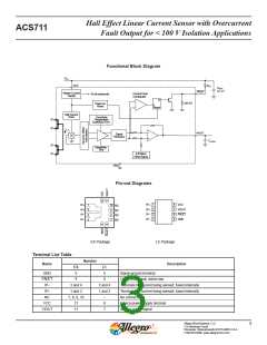
Functional Block Diagram
VCC
VCC
RPU
CBYP
FAULT
Master Current
Supply
Current Fault
Comparator
To all subcircuits
D
240 kΩ
Power-on
Reset
Reset
Hall Current
Drive
Sensitivity
Temperature
Coefficient Trim
IP+
IP+
VIOUT
Signal
Recovery
CLOAD
IPꢀ
IPꢀ
Sensitivity
Trim
0 Ampere
Offset Adjust
GND
Pin-out Diagrams
IP+
1
8
7
6
5
VCC
IP+
IP+
IP–
IP–
1
2
3
4
10
9
NC
IP+
2
3
4
VIOUT
FAULT
GND
NC
IP–
8
NC
IP–
7
NC
EX Package
LC Package
Terminal List Table
Number
Name
Description
EX
5
LC
5
GND
Signal ground terminal
¯¯¯¯¯¯¯¯¯
FAULT
6
6
Overcurrent fault; active low
IP–
IP+
3 and 4
1 and 2
7, 8, 9, 10
12
3 and 4
Terminals for current being sensed; fused internally
Terminals for current being sensed; fused internally
No connection
1 and 2
NC
–
8
7
VCC
VIOUT
Device power supply terminal
11
Analog output signal
Allegro MicroSystems, LLC
115 Northeast Cutoff
3
Worcester, Massachusetts 01615-0036 U.S.A.
1.508.853.5000; www.allegromicro.com

 ALLEGRO [ ALLEGRO MICROSYSTEMS ]