Isolated, Digital Output, Power Monitoring IC
with Zero-Crossing Detection, Overcurrent and Overvoltage Flagging
ACS37800
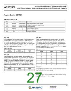
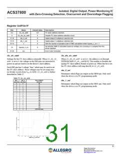
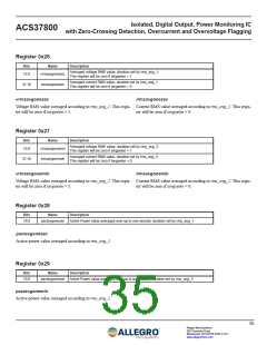
Register 0x0F/0x1F
Bits
8:2
Name
i2c_slv_addr
i2c_dis_slv_addr
dio_0_sel
dio_1_sel
n
Default Value
Description
127
0
I2C slave address selection
9
Disable I2C slave address selection circuit
Digital output 0 multiplexor selection bits
Digital output 1 multiplexor selection bits
Sets the number of samples used in RMS calculations when bypass_n_en = 1
11:10
13:12
23:14
0
0
0
Set whether RMS is calculated based on voltage zero crossing or n samples from the
above registers
24
bypass_n_en
ecc
0
–
31:26
Error Code Correction
i2c_slv_addr
i2c_dis_slv_addr
Settings for the I2C slave address externally. When i2c_dis_slv_
addr is set to 0, the voltage on the DIO pins are measured at
power on and are used to set the device’s slave address.
When i2c_dis_slv_addr is set to 1, the address is set through
EEPROM field i2c_slv__addr[6:0]. This enables or disables the
analog I2C slave address feature at power on. When this bit is set,
the I2C slave address will map directly to i2c_slv_addr.
Each DIO pin has 4 voltage “bins” which may be used to set
the I2C slave address. These voltages may be set using resis-
tor divider circuits from VCC to GND. i2c_slv_addr is further
described in Table 17.
dio_0_sel
Determines which flags are output on the DIO0 pin. Only used
when the device is in I2C programming mode.
Table 17: i2c_slv_addr
DIO_1
(decimal) (decimal)
DIO_0
Slave Address
(decimal)
dio_1_sel
0
0
0
0
1
1
1
1
2
2
2
2
3
3
3
3
0
1
2
3
0
1
2
3
0
1
2
3
0
1
2
3
96
Determines which flags are output on the DIO1 pin. Only used
when the device is in I2C programming mode.
97
98
99
100
101
102
103
104
105
106
107
108
109
110
EEPROM value
Ratio of VCC on DIO Pin
31
Allegro MicroSystems
955 Perimeter Road
Manchester, NH 03103-3353 U.S.A.
www.allegromicro.com

 ALLEGRO [ ALLEGRO MICROSYSTEMS ]