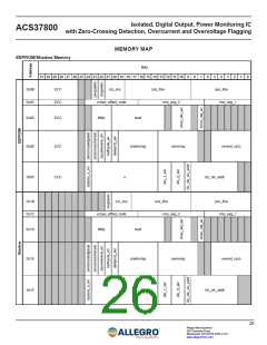
Isolated, Digital Output, Power Monitoring IC
with Zero-Crossing Detection, Overcurrent and Overvoltage Flagging
ACS37800
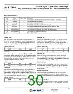
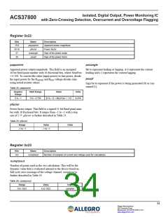
Register 0x0E/0x1E
Bits
5:0
Name
vevent_cycs
overvreg
Default Value Description
0
0
0
0
0
0
0
0
–
Sets the number of qualifying cycles needed to flag overvoltage or undervoltage
Sets the overvoltage fault threshold
13:8
19:14
20
undervreg
Sets the undervoltage fault threshold
delaycnt_sel
halfcyclc_en
squarewave_en
zerocrosschansel
zerocrossedgesel
ecc
Sets the width of the voltage zero-crossing output pulse
Sets the zero crossing flag triggering on half or full cycle (default: full cycle)
Sets the zero crossing pulse characteristics (default: pulse)
Sets the channel that triggers the zero crossing flag (default: voltage)
Sets the edge that triggers zero crossing flag
21
22
23
24
31:26
Error Code Correction
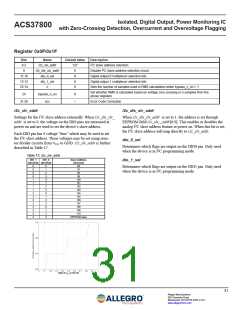
vevent_cycs
delaycnt_sel
Sets the number of cycles required to assert the ovrms flag or
the uvrms. This is an unsigned 6-bit number with an input range
of 0 to 63. The value in this field directly maps to the number of
cycles. vevent_cycs is further described in Table 13.
Selection bit for the width of pulse for a voltage zero-crossing
event. When set to 0, the pulse is 32 µs. When set to 1, the
pulse is 256 µs. When the squarewave_en bit is set, this field is
ignored. delaycnt_sel is further described in Table 16.
Table 13: vevent_cycs
Table 16: delaycnt_sel
Range
Value
Units
Range
Value
32
Units
µs
0 to 63
1 to 64
cycles
0
1
256
µs
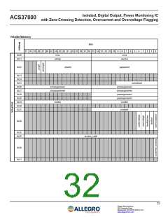
overvreg
halfcycle_en
Sets the threshold of the overvoltage rms flag (ovrms). This is a
6-bit number ranging from 0 to 63. This trip level spans the entire
range of the vrms register. The flag is set if the rms value is above
this threshold for the number of cycles selected in vevent_cycs.
overvreg is further described in Table 14.
Setting for the zero crossing flag. When set to 0, the voltage
zero-crossing will be indicated on every edge determined by
zerocrossingedgesel. When set to 1, the voltage zero-crossing will
be indicated on both rising and falling edges.
Table 14: overvreg
squarewave_en
Range
Value
Units
Setting for the zero crossing flag. When set to 0, the zero-cross-
ing event will be indicated by a pulse on the DIO pin. When set
to 1, the zero-crossing event will be indicated by a level change
on the DIO pin.
0 to 63
0 to 65536
LSB
undervreg
Sets the threshold of the undervoltage rms flag (uvrms). This is
a 6-bit number ranging from 0 to 63. This trip level spans one
entire range of the vrms register. The flag is set if the rms value is
below this threshold for the number of cycles selected in vevent_
cycs. undervreg is further described in Table 15.
zercrossingchansel
Determines which channel will trigger the zero crossing flag. 0
is the voltage channel. 1 is the current channel with zero cross-
ing flag for rising and falling with only one customizable register
delaycnt_sel.
Table 15: undervreg
zerocrossingedgesel
Range
Value
Units
0 to 63
0 to 65536
LSB
This determines whether the zero crossing flag triggers on rising
or falling. Note: if halfcycle_en = 1, this setting does not matter.
30
Allegro MicroSystems
955 Perimeter Road
Manchester, NH 03103-3353 U.S.A.
www.allegromicro.com

 ALLEGRO [ ALLEGRO MICROSYSTEMS ]