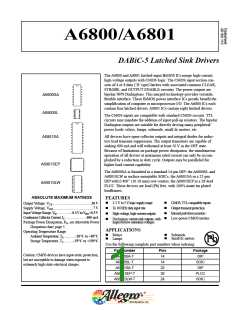
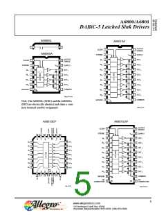
A6800/A6801
DABiC-5 Latched Sink Drivers
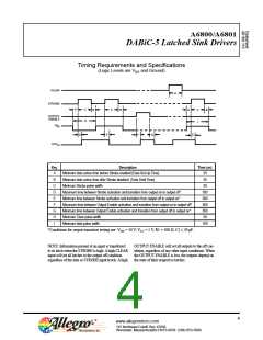
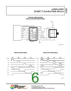
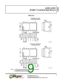
Timing Requirements and Specifications
(Logic Levels are VDD and Ground)
CLEAR
H
STROBE
A
C
G
B
B
C
C
I
A
B
OUTPUT
ENABLE
IN
N
E
E
D
F
G
OUT
N
Key
A
Description
Time (ns)
25
Minimum data active time before Strobe enabled (Data Set-Up Time)
Minimum data active time after Strobe disabled (Data Hold Time)
Minimum Strobe pulse width
B
25
C
D
E
50
Maximum time between Strobe activation and transition from output on to output off*
Minimum time between Strobe activation and transition from output off to output on*
500
500
500
500
50
F
Maximum time between Output Enable activation and transition from output on to output off*
Minimum time between Output Enable activation and transition from output off to output on*
Minimum Clear pulse width
G
H
I
Minimum data pulse width
100
*Conditions for output transition testing are: VDD = 50 V, VCC = 5 V, R1 = 500 Ω, C1 ≤ 30 pF.
NOTE: Information present at an input is transferred
to its latch when the STROBE is high. A high CLEAR
input will set all latches to the output off condition
regardless of the data or STROBE input levels. A high
OUTPUT ENABLE will set all outputs to the off con-
tdition, regardless of any other input conditions. When
the OUTPUT ENABLE is low, the outputs depend on
the state of their respective latches.
4
www.allegromicro.com
115 Northeast Cutoff, Box 15036
Worcester, Massachusetts 01615-0036 (508) 853-5000

 ALLEGRO [ ALLEGRO MICROSYSTEMS ]