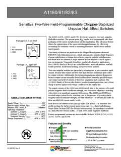
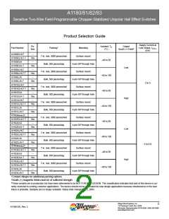
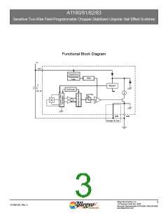
A1180/81/82/83
Sensitive Two-Wire Field-Programmable Chopper-Stabilized Unipolar Hall Effect Switches
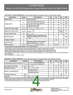
ELECTRICAL CHARACTERISTICS over the operating voltage and temperature range, unless otherwise specified
Characteristic
Supply Voltage1
Symbol
Test Conditions
Device powered on
Min.
3.5
2
Typ.
Max.
24
Units
V
VCC
–
–
–
B >BOP for A1180; B <BRP for A1181
B >BOP for A1182; B <BRP for A1183
5
mA
mA
ICC(L)
5
6.9
Supply Current2
B >BOP for A1181, A1183
B <BRP for A1180, A1182
ICC(H)
12
28
–
–
–
–
17
mA
V
Supply Zener Clamp Voltage
Supply Zener Clamp Current
Reverse Supply Current
VZ(supply) ICC = ICC(L)(max) + 3 mA; TA = 25°C
40
ICC(L)(max)
+ 3 mA
IZ(supply)
IRCC
VZ(supply) = 28 V
mA
VRCC = –18 V
–
–
–
–1.6
mA
No bypass capacitor; capacitance of the
oscilloscope performing the measurement
= 20 pF
Output Slew Rate3
di/dt
36
–
mA/μs
Chopping Frequency
Power-On Time4
fC
ton
–
–
–
200
–
–
25
–
kHz
μs
–
After factory trimming; with and without
bypass capacitor (CBYP = 0.01 μF)
Power-On State5,6
POS
ton ≤ ton(max); VCC slew rate ≥ 25 mV/μs
HIGH
1VCC represents the generated voltage between the VCC pin and the GND pin.
2Relative values of B use the algebraic convention, where positive values indicate south magnetic polarity, and negative values indicate north magnetic
polarity; therefore greater B values indicate a stronger south polarity field (or a weaker north polarity field, if present).
3Measured without bypass capacitor between VCC and GND. Use of a bypass capacitor results in slower current change.
4Measured with and without bypass capacitor of 0.01 μF. Adding a larger bypass capacitor causes longer Power-On Time.
5POS is defined as true only with a VCC slew rate of 25 mV/μs or greater. Operation with a VCC slew rate less than 25 mV/μs can permanently harm
device performance.
6POS is undefined for t > ton or BRP < B < BOP
.
MAGNETIC CHARACTERISTICS1 over the operating voltage and temperature range, unless otherwise specified
Characteristic
Symbol
Test Conditions
Min.
Typ.
Max.
Units
ICC = ICC(H) for A1180 and A1182
ICC = ICC(L) for A1181 and A1183
Programmable Operate Point Range BOPrange
60
–
200
G
Initial Operate Point Range
Switchpoint Step Size2
BOPinit
BRES
VCC = 12 V
–
4
–
–
–
5
33
8
60
12
–
G
G
VCC = 5 V, TA = 25°C
Switchpoint setting
Programming locking
5
Bit
Bit
G
Number of Programming Bits
–
1
–
Temperature Drift of BOP
Hysteresis
ΔBOP
–
±20
30
BHYS
BHYS = BOP – BRP
15
G
1Relative values of B use the algebraic convention, where positive values indicate south magnetic polarity, and negative values indicate north magnetic
polarity; therefore greater B values indicate a stronger south polarity field (or a weaker north polarity field, if present).
2The range of values specified for BRES is a maximum, derived from the cumulative programming bit errors.
Allegro MicroSystems, Inc.
4
115 Northeast Cutoff, Box 15036
A1180-DS, Rev. 2
Worcester, Massachusetts 01615-0036 (508) 853-5000
www.allegromicro.com

 ALLEGRO [ ALLEGRO MICROSYSTEMS ]