[AK4679]
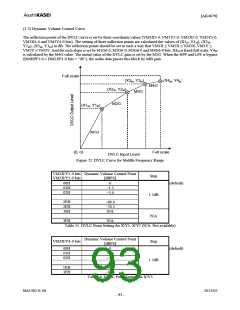
(1-2) Dynamic Volume Control Curve
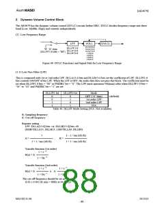
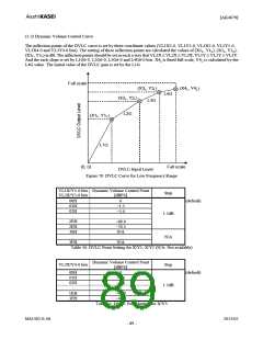
The inflection points of the DVLC curve is set by three coordinate values (VL1X5-0, VL1Y5-0, VL2X5-0, VL2Y5-0,
VL3X4-0 and VL3Y4-0 bits). The setting of three inflection points are calculated the values of (X1L, Y1L), (X2L, Y2L),
(X3L, Y3L) in dB. The inflection points should be set in such a way that VL1X ≤ VL2X ≤ VL3X, VL1Y ≤ VL2Y ≤ VL3Y.
And the each slope is set by L1G6-0, L2G6-0, L3G6-0 and L4G6-0 bits. X4L is fixed full-scale, Y4L is calculated by the
L4G value. The initial value of the DVLC gain is set by the L1G.
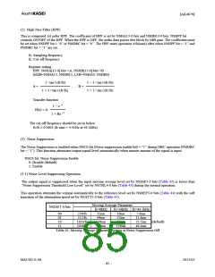
Full scale
(X3L, Y3L)
L3G
(X4L, Y4L)
L4G
(X2L, Y2L)
L2G
(X1L, Y1L)
L1G
(0, 0)
Full scale
DVLC Input Level
Figure 70. DVLC Curve for Low Frequency Range
VL1X/Y5-0 bits Dynamic Volume Control Point
Step
VL2X/Y5-0 bits
[dBFS]
00H
01H
02H
:
0
(default)
−1.5
−3.0
:
1.5dB
2EH
2FH
30H
:
−69.0
−70.5
N/A
:
N/A
3FH
N/A
Table 50. DVLC Point Setting for X/Y1, X/Y2 (N/A: Not available)
Dynamic Volume Control Point
VL3X/Y4-0 bits
Step
[dBFS]
0
−1.5
−3.0
:
00H
01H
02H
:
(default)
1.5dB
1EH
1FH
−45.0
−46.5
Table 51. DVLC Point Setting for X/Y3
MS1402-E-06
2013/02
- 89 -

 AKM [ ASAHI KASEI MICROSYSTEMS ]