[AK4675]
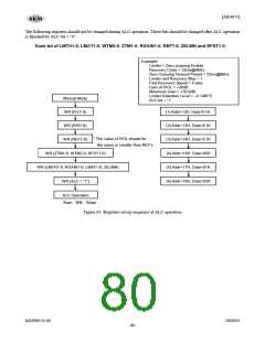
The following registers should not be changed during ALC operation. These bits should be changed after ALC operation
is finished by ALC bit = “0”.
Each bit of LMTH1-0, LMAT1-0, WTM2-0, ZTM1-0, RGAIN1-0, REF7-0, ZELMN and RFST1-0.
Example:
Limiter = Zero crossing Enable
Recovery Cycle = 32ms@8kHz
Zero Crossing Timeout Period = 32ms@8kHz
Limiter and Recovery Step = 1
Fast Recovery Speed = 4 step
Gain of IVOL = +30dB
Maximum Gain = +30.0dB
Limiter Detection Level = −4.1dBFS
Manual Mode
ALC bit = “1”
WR (IVL7-0)
WR (IVR7-0)
WR (REF7-0)
(1) Addr=12H, Data=E1H
(2) Addr=13H, Data=E1H
(3) Addr=14H, Data=E1H
* The value of IVOL should be
the same or smaller than REF’s
WR (ZTM1-0, WTM2-0, RFST1-0)
WR (LMTH1-0, RGAIN1-0, LMAT1-0, ZELMN)
WR (ALC = “1”)
(4) Addr=16H, Data=05H
(5) Addr=17H, Data=01H
(6) Addr=18H, Data=03H
ALC Operation
Note : WR : Write
Figure 61. Registers set-up sequence at ALC operation
MS0963-E-00
2008/05
- 80 -

 AKM [ ASAHI KASEI MICROSYSTEMS ]