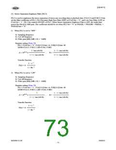
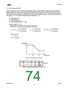
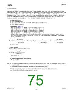
[AK4675]
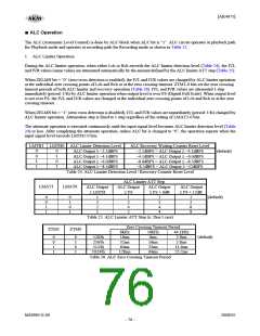
2. ALC Recovery Operation
ALC recovery operation waits for the WTM2-0 bits (Table 27) to be set after completing ALC limiter operation. If the
input signal does not exceed “ALC recovery waiting counter reset level” (Table 24) during the wait time, ALC recovery
operation is executed. The IVL and IVR values are automatically incremented by RGAIN1-0 bits (Table 28) up to the set
reference level (Table 29) with zero crossing detection which timeout period is set by ZTM1-0 bits (Table 26). Then the
IVL and IVR are set to the same value for both channels. ALC recovery operation is executed at a period set by WTM2-0
bits. When zero cross is detected at both channels during the wait period set by WTM2-0 bits, ALC recovery operation
waits until WTM2-0 period and the next recovery operation is executed. If ZTM1-0 is longer than WTM2-0 and no zero
crossing occurs, the ALC recovery operation is executed at a period set by ZTM1-0 bits.
For example, when the current IVL and IVR values are 30H and RGAIN1-0 bits are set to “01”, IVL and IVR values are
changed to 32H by the auto limiter operation and then the input signal level is gained by 0.75dB (=0.375dB x 2). When
the IVL and IVR values exceed the reference level (REF7-0 bits), the IVL and IVR values are not increased.
When
“ALC recovery waiting counter reset level (LMTH1-0) ≤ Output Signal < ALC limiter detection level (LMTH1-0)”
during the ALC recovery operation, the waiting timer of ALC recovery operation is reset. When
“ALC recovery waiting counter reset level (LMTH1-0) > Output Signal”,
the waiting timer of ALC recovery operation starts.
The ALC operation corresponds to the impulse noise. When the impulse noise is input, the ALC recovery operation
becomes faster than a normal recovery operation (Fast Recovery Operation). When large noise is input to microphone
instantaneously, the quality of small level in the large noise can be improved by this fast recovery operation. The speed of
fast recovery operation is set by RFST1-0 bits (Table 30).
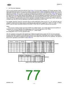
ALC Recovery Operation Waiting Period
WTM2
WTM1
WTM0
8kHz
16kHz
44.1kHz
0
0
0
0
1
1
1
1
0
0
1
1
0
0
1
1
0
1
0
1
0
1
0
1
128/fs
256/fs
512/fs
1024/fs
2048/fs
4096/fs
8192/fs
16384/fs
16ms
32ms
64ms
128ms
256ms
512ms
1024ms
2048ms
8ms
16ms
32ms
64ms
128ms
256ms
512ms
1024ms
2.9ms
5.8ms
(default)
11.6ms
23.2ms
46.4ms
92.9ms
185.8ms
371.5ms
Table 27. ALC Recovery Operation Waiting Period
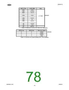
RGAIN1
RGAIN0
GAIN STEP
1 step 0.375dB (default)
0
0
1
1
0
1
0
1
2 step
3 step
4 step
0.750dB
1.125dB
1.500dB
Table 28. ALC Recovery GAIN Step
MS0963-E-00
2008/05
- 77 -

 AKM [ ASAHI KASEI MICROSYSTEMS ]