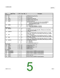
ASAHI KASEI
[AK4571]
No.
Signal Name
I/O
Ana / Dig
Description
EEPROM I/F
31
32
34
33
35
CS
O
O
I
D
D
D
D
D
EEPROM I/F Chip Select Pin
Read Clock Pin
SK
EPDI
EPAO
EPEN
EEPROM Data Input Pin
EEPROM Address Output Pin
EEPROM Enable Pin
O
I
"H": Read Device/String Descriptor from external EEPROM
”L”: Read Device/String Descriptor from internal ROM.
CS,SK,EPDI,EPAO are Hi-Z
36
EPSEL
I
I
D
D
EEPROM Select
“L”: 1Kbit Type EEPROM is connected.
“H”: 2Kbit/4Kbit EEPROM is connected
HID Interface
39
IMUTE
A/D Mute
Toggles mute status at the rising edge. If this pin is not used, please
connect this pin to DGND.
43
41
42
40
OMUTE
INC
I
I
D
D
D
D
D/A Mute
Sets “1” to internal register at the rising edge, and reset to “0” at the
falling edge. If this pin is not used, please connect this pin to DGND.
D/A Volume Up Pin
Sets “1” to internal register at the rising edge, and reset to “0” at the
falling edge. If this pin is not used, please connect this pin to DGND.
D/A Volume Down Pin
Sets “1” to internal register at the rising edge, and reset to “0” at the
falling edge. If this pin is not used, please connect this pin to DGND.
Recording Mute Status Pin.
DEC
I
MSTAT
O
“H”: Mute ON
“L”: Mute OFF
In suspend mode, this pin is “L”.
Power Supply
25
26
VA
AGND
P
P
A
A
Analog Power Supply, 3.3V
Analog Ground
1
2
VD
DGND
P
P
D
D
Digital Power Supply, 3.3V
Digital Ground
3
BGND
P
D
Bulk Ground, 0V
Test Mode
18
29
30
38
TESTMODE1
I
I
I
I
Please tie down to AGND for normal operation.
Please tie down to AGND for normal operation.
Please tie down to AGND for normal operation.
Please tie down to DGND for normal operation.
TESTMODE2
TESTMODE3
TEST1
37
48
TEST2
TEST3
O
I
Please open state
Please tie down to DGND for normal operation.
MS0153-J-02
2003/3
- 5 -

 AKM [ ASAHI KASEI MICROSYSTEMS ]