ASAHI KASEI
[AK4393]
ABSOLUTE MAXIMUM RATINGS
(AVSS, BVSS, DVSS = 0V; Note 1)
Parameter
Symbol
AVDD
DVDD
D GND
IIN
VIND
Ta
Tstg
min
-0.3
-0.3
-
max
6.0
6.0
Units
V
V
V
mA
V
Power Supplies:
Analog
Digital
| BVSS-DVSS | (Note 2)
0.3
Input Current , Any pin Except Supplies
Input Voltage
Ambient Operating Temperature
Storage Temperature
-
±10
DVDD+0.3
85
-0.3
-40
-65
°C
°C
150
Notes: 1. All voltages with respect to ground.
2. AVSS, BVSS and DVSS must be connected to the same analog ground plane.
WARNING: Operation at or beyond these limits may result in permanent damage to the device.
Normal operation is not guaranteed at these extremes.
RECOMMENDED OPERATING CONDITIONS
(AVSS, BVSS, DVSS=0V; Note 1)
Parameter
Power Supplies:
(Note 3)
Voltage Reference
(Note 4)
Symbol
AVDD
DVDD
VREFH
VREFL
D VREF
min
4.75
3.0
typ
5.0
3.3
-
-
-
max
5.25
5.25
AVDD
-
AVDD
Units
V
V
V
V
Analog
Digital
“H” voltage reference
“L” voltage reference
VREFH-VREFL
AVDD-0.5
AVSS
3.0
V
Notes: 3. The power up sequence between AVDD and DVDD is not critical.
4. Analog output voltage scales with the voltage of (VREFH-VREFL).
AOUT (typ.@0dB) = (AOUT+) - (AOUT-) = ±2.4Vpp×(VREFH-VREFL)/5.
* AKM assumes no responsibility for the usage beyond the conditions in this data sheet.
M0039-E-01
2000/5
- 4 -

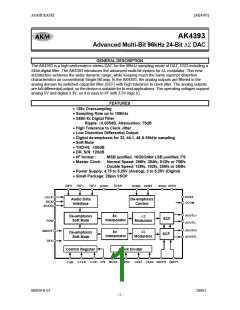
 AKM [ ASAHI KASEI MICROSYSTEMS ]