5
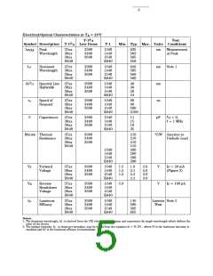
Electrical/Optical Characteristics at T = 25°C
A
3
T-1 /
Test
Min. Typ. Max. Units Conditions
4
3
Symbol Description
T-1 /
Low Dome
T-1
4
λ
Peak
37xx
38xx
39xx
3390
3490
3590
1340
1440
1540
K640
635
583
565
558
nm
nm
nm
ns
Measurement
at Peak
PEAK
Wavelength
D640
λ
Dominant
Wavelength
37xx
38xx
39xx
D640
3390
3490
3590
1340
1440
1540
K640
626
585
569
560
Note 1
d
3
∆λ /
Spectral Line 37xx
Halfwidth
3390
3490
3590
1340
1440
1540
K640
40
36
28
24
4
38xx
39xx
D640
τ
Speed of
Respond
37xx
38xx
39xx
D640
3390
3490
3590
1340
1440
1540
K640
90
90
500
3100
s
C
Capacitance
37xx
38xx
39xx
D640
3390
3490
3590
1340
1440
1540
K640
11
15
18
35
pF
V = 0,
F
f = 1 MHz
Rθ
Thermal
Resistance
37xx
38xx
39xx
D640
3390
3490
3590
210
210
210
510
290
290
290
290
°C/W Junction to
J-PIN
Cathode Lead
1340
1440
1540
K640
V
Forward
Voltage
37xx
38xx
39xx
D640
3390
3490
3590
1340
1440
1540
K640
1.5
1.5
1.5
1.9
2.1
2.2
2.2
2.6
2.6
3.0
3.0
V
V
I = 20 mA
F
R
v
F
(Figure 3)
V
Reverse
Breakdown
Voltage
37xx
38xx
39xx
D640
3390
3490
3590
1340
1440
1540
K640
5.0
I = 100 µA
F
η
Luminous
Efficacy
37xx
38xx
39xx
D640
3390
3490
3590
1340
1440
1540
K640
145
500
595
655
Lumens Note 2
Watt
Notes:
1. The dominant wavelength, ld , is derived from the CIE chromaticity diagram and represents the single wavelength which defines the
color of the device.
2. The radiant intensity, Ie , in watts per steradian, may be found from the equation Ie = IV /hV , where IV is the luminous intensity in
candelas and hV is the luminous efficacy in lumens/watt.

 AGILENT [ AGILENT TECHNOLOGIES, LTD. ]