4
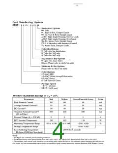
Part Numbering System
HLMP - x x xx - x x x xx
Mechanical Options
00: Bulk
01: Tape & Reel, Crimped Leads
02, Bx: Tape & Reel, Straight Leads
A1,B1: Right Angle Housing, Uneven Leads
A2,B2: Right Angle Housing, Even Leads
Dx, Ex: Ammo Pack, Straight Leads
FH: 2 Iv bin select with Inventory Control
Vx: Ammo Pack, Crimped Leads
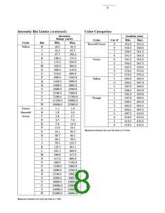
Color Bin Options
0: Full color bin distribution
B: Color bin 2&3 only
N: Color bin 6&7 only
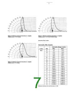
Maximum Iv Bin Options
0: Open (No. max. limit)
Others: Please refer to the Iv bin table
Minimum Iv Bin Options
Please refer to the Iv bin table
Color Options
3,7: GaP HER
4,8: GaP Yellow (except K4xx series)
5,9: GaP Green
6: GaP Emerald Green
Package Option
1,K: T-1 (3 mm)
3
3,D: T-1 / (5 mm)
4
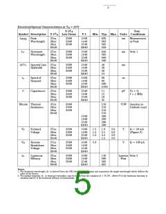
Absolute Maximum Ratings at TA = 25°C
Parameter
Peak Forward Current
Average Forward Current[1]
DC Current[2]
Red
90
Yellow
60
Green/Emerald Green
Units
mA
90
25
25
20
mA
30
20
30
mA
Transient Forward Current[3]
500
500
500
mA
(10 µs Pulse)
Reverse Voltage (IR = 100 µA)
LED Junction Temperature
Operating Temperature Range
Storage Temperature Range
5
5
5
V
110
110
110
°C
°C
-55 to +100 -55 to +100
-20 to +100
-55 to +100
Lead Soldering Temperature
260°C for 5 seconds
[1.6 mm (0.063 in.) from body]
Notes:
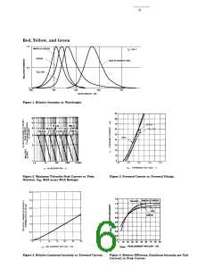
1. See Figure 2 to establish pulsed operating conditions.
2. For Red and Green series derate linearly from 50°C at 0.5 mA/°C. For Yellow series derate linearly from 50°C at 0.2 mA/°C.
3. The transient peak current is the maximum non-recurring peak current the devices can withstand without damaging the LED die and
wire bonds. It is not recommended that the device be operated at peak currents beyond the Absolute Maximum Peak Forward Current.

 AGILENT [ AGILENT TECHNOLOGIES, LTD. ]